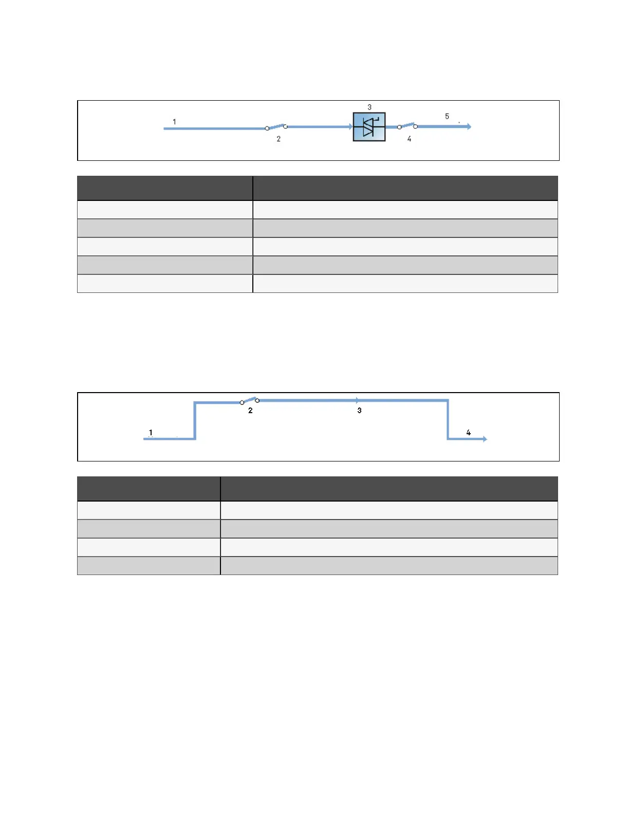
Figure 2.5 Schem atic diagram of bypass m ode
N o. Descriptio n
1 Bypass input
2 Bypass input switch
3 Static switch
4 Output switch
5 UPS output
Maintenance mode
As shown in Figure 2.6 below, if the UPS maintenance or service is required, you may use the manual maintenance bypass
switch to transfer the load to maintenance bypass, with no interruption in power to the load. This maintenance bypass switch
is fitted in all UPS modules and rated for full load of a single module.
Figure 2.6 Sch em atic diagram of m aintenance m od e
N o. Descriptio n
1 Bypass input
2 Maintenance bypass switch
3 Maintenance bypass
4 UPS output
ECO mode
If ECO mode is selected, all the power switches and the battery switches are closed except for the maintenance bypass
switch, and the system prefers to put the load on the bypass, to achieve the aim of energy-saving. When the bypass supply is
within the range of normal frequency and normal voltage (adjustable), the load is powered by the bypass, with the inverter on
stand-by; when the voltage and/or frequency of the bypass supply are beyond the pre-defined and adjustable limits, the
system will transfer to the inverter output, and the transfer time for switching from bypass to inverter is less than 2ms
(uninterrupted) and less than 5ms (interrupted). In this mode, the system can normally charge the battery.
2 Overview
11
Vertiv™ Liebert® APM Plus User Manual