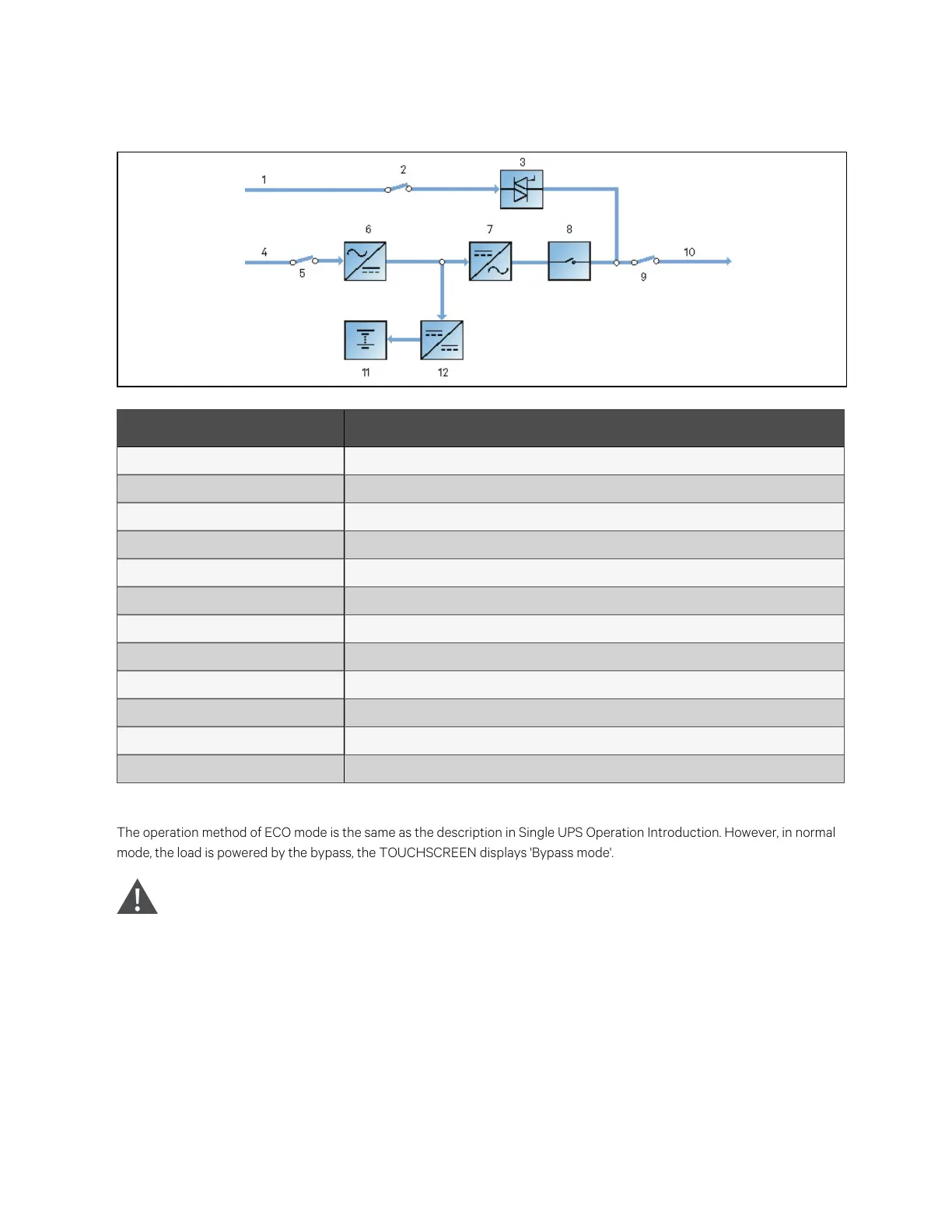
Figure 2.7 Schem atic diagram of EC O m ode
N o. Descriptio n
1 Bypass input
2 Bypass input switch
3 Static switch
4 Mains input
5 Rectifier input switch
6 Rectifier
7 Inverter
8 Automatic inverter switch
9 Output switch
10 UPS output
11 Battery
12 Battery charger
If ECO mode is required, adjust corresponding parameters through the touch screen.
The operation method of ECO mode is the same as the description in Single UPS Operation Introduction. However, in normal
mode, the load is powered by the bypass, the TOUCHSCREEN displays 'Bypass mode'.
W ARN ING ! In ECO m o de, the load is not protected ag ainst m ain s d isto rtion.
2 Overview
12
Vertiv™ Liebert® APM Plus User Manual