7.12 Design of Battery Room
Pay attention to the below items while designing the battery room.
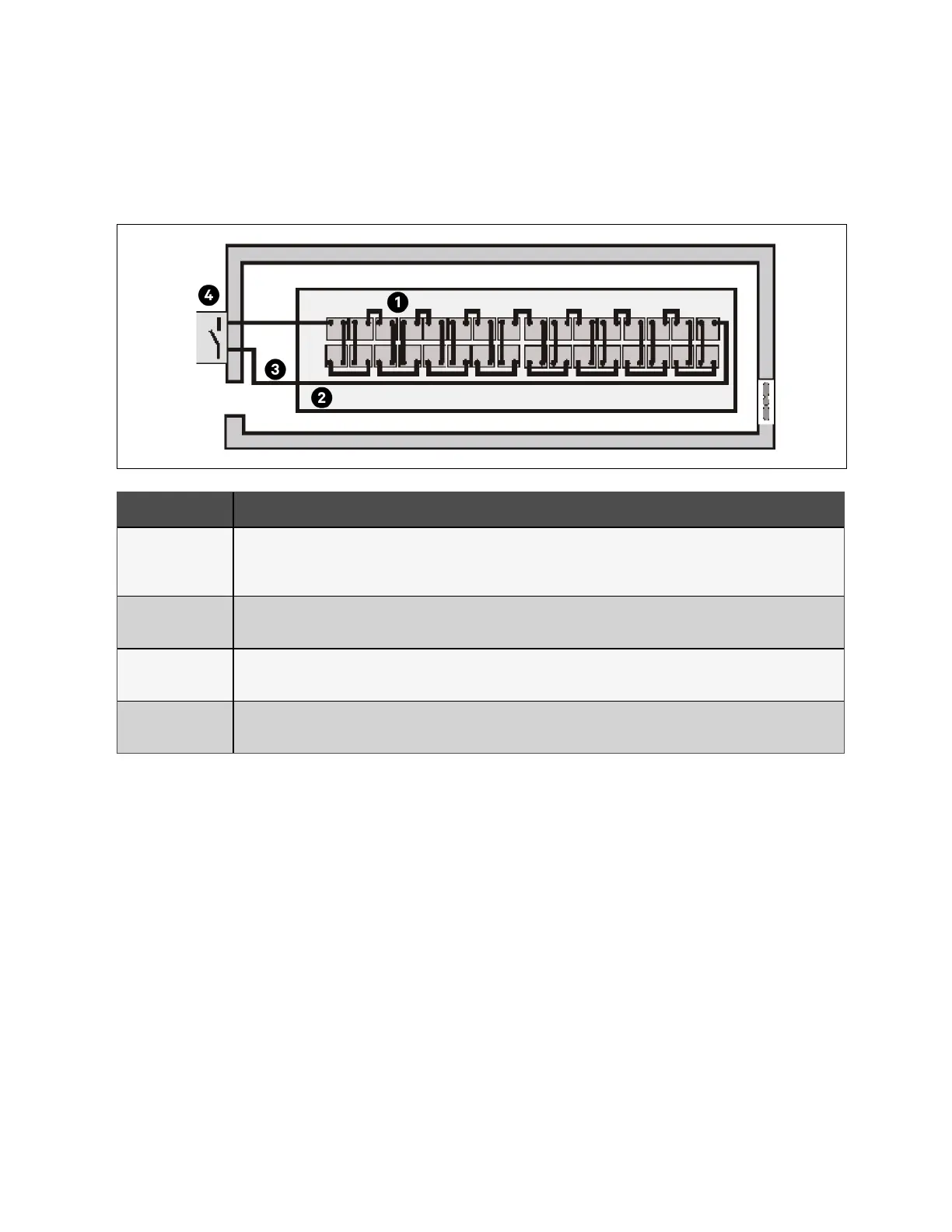
Figure 7.5 Design of Battery Room
Item Description
1
Layout of cells
The battery should not get in contact with 2 naked live parts with the potential difference over 150 V at the same time. If it is
unavoidable, insulated terminal shield and insulated cable must be used for the connection.
2
Workbench
The workbench (or pedal) must be skid proof and insulated, and at least 1 m wide.
3
Wiring
All the wiring distances should be minimized.
4
BCB
The BCB is generally installed in the wall mounted box near the battery.
7.13 Common Battery String
The UPS supports common battery string function, which indicates that each unit in the parallel system shares the same
battery string for energy saving, space saving and efficiency improving. The cables connection for common battery string is
shown in Figure 7.6 on the next page. Make sure that the below requirements are fulfilled before connecting the common
battery string:
1. All the units in parallel system share the same battery string, and no intermixing of common battery string with
independent battery.
2. Each unit should use the common battery string.
3. Each UPS has its own BCB box.
7 Battery Proprietary and Confidential ©2023 Vertiv Group Corp. 133
Vertiv™ Liebert® APM2 30 to 120 kVA Modular UPS User Manual