4.2.4 Output dry contact X7 J1 (option)
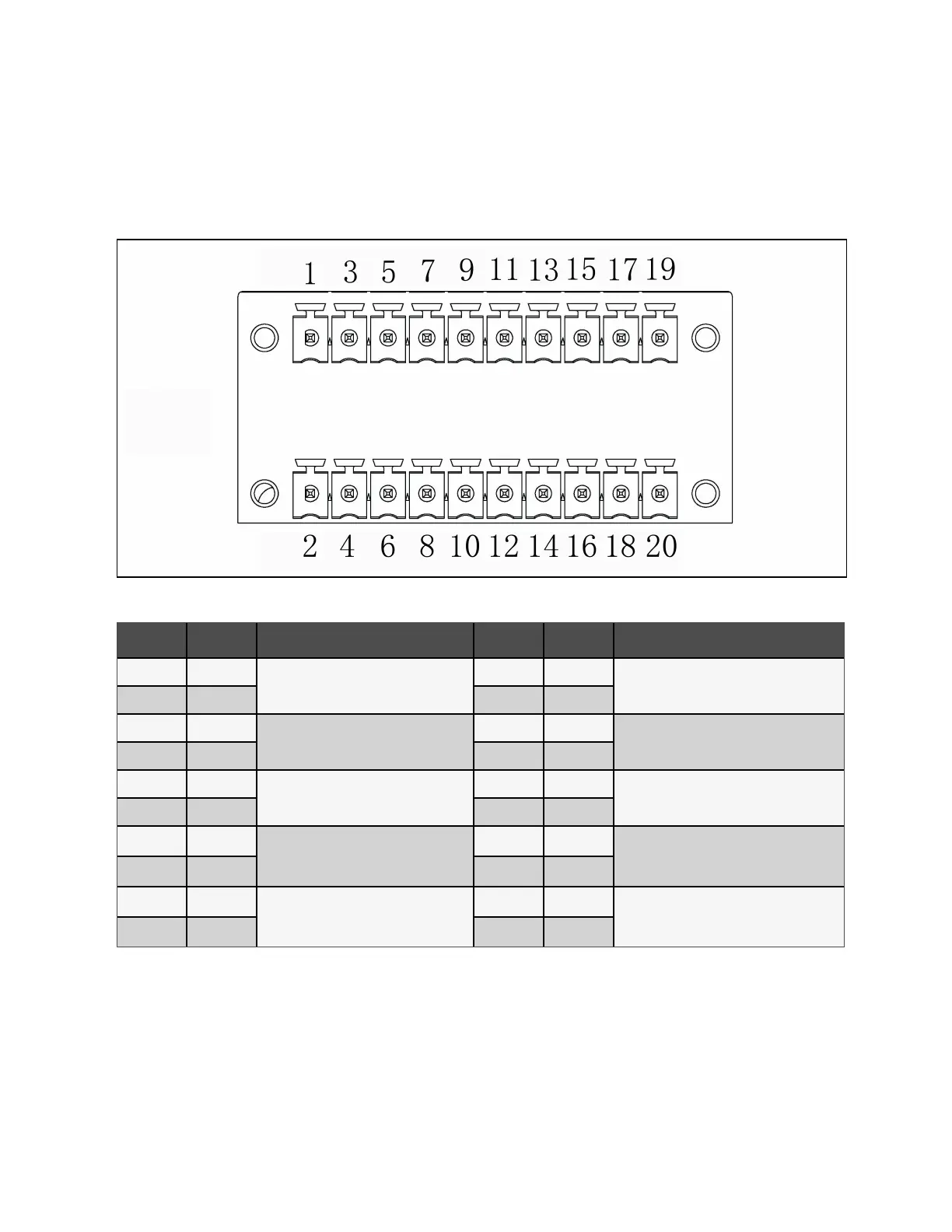
The schematic diagram of output dry contact port J1 is shown in Figure 4.8 below and described in Table 4.7 below. The dry
contact voltage is 24 VDC/250 VAC and the current is 5 A.
Figure 4.8 Dry Contact Port J1
Pin Name Meanings Pin Name Meanings
1 BCB_Drive2
BCB2 trip signal
2 BCB_Drive3
BCB3 drive signal.
3 GND 4 GND
5 Dry in
Input dry contact can be defined, the
default setting is BCB2 status feedback.
6 Dry in
Input dry contact can be defined, the default
setting is BCB3 status feedback.
7 GND 8 GND
9 Dry in
The input dry contact can be defined, and
the default setting is BCB2 enable signal.
10 Dry in
The input dry contact can be defined, and the
default setting is BCB3 enable signal.
11 GND 12 GND
13 Dry in
The input dry contact can be defined, and
the default setting is to turn off the inverter.
14 Dry in
The input dry contact can be defined, and the
default setting is the state of the external
output switch MOB/QE.
15 GND 16 GND
17 Dry in
The input dry contact can be defined, and
the default setting is the maintenance
switch MBB/QBP state.
18 Dry in
The input dry contact can be defined, and the
default setting is the state of the system total
output switch MIB/QOP.
19 GND 20 GND
Table 4.7 Description of Dry Contact Port J1
NOTE: The programmable dry contacts must be set in Paramset.
When using parallel system, if you want to use the dry contact function of the external maintenance isolation circuit breaker,
the auxiliary contact signal must be connected to the respective dry contacts on all single racks in the parallel system at the
same time.
4 Electrical Installation Proprietary and Confidential ©2023 Vertiv Group Corp. 45
Vertiv™ Liebert® APM2 30 to 120 kVA Modular UPS User Manual