NOTE: The external EPO device is consists of another control system which can disconnect UPS mains supply or
bypass input. Pins 1 and 2 of the normally closed EPO port on the integrated control module is linked in factory.
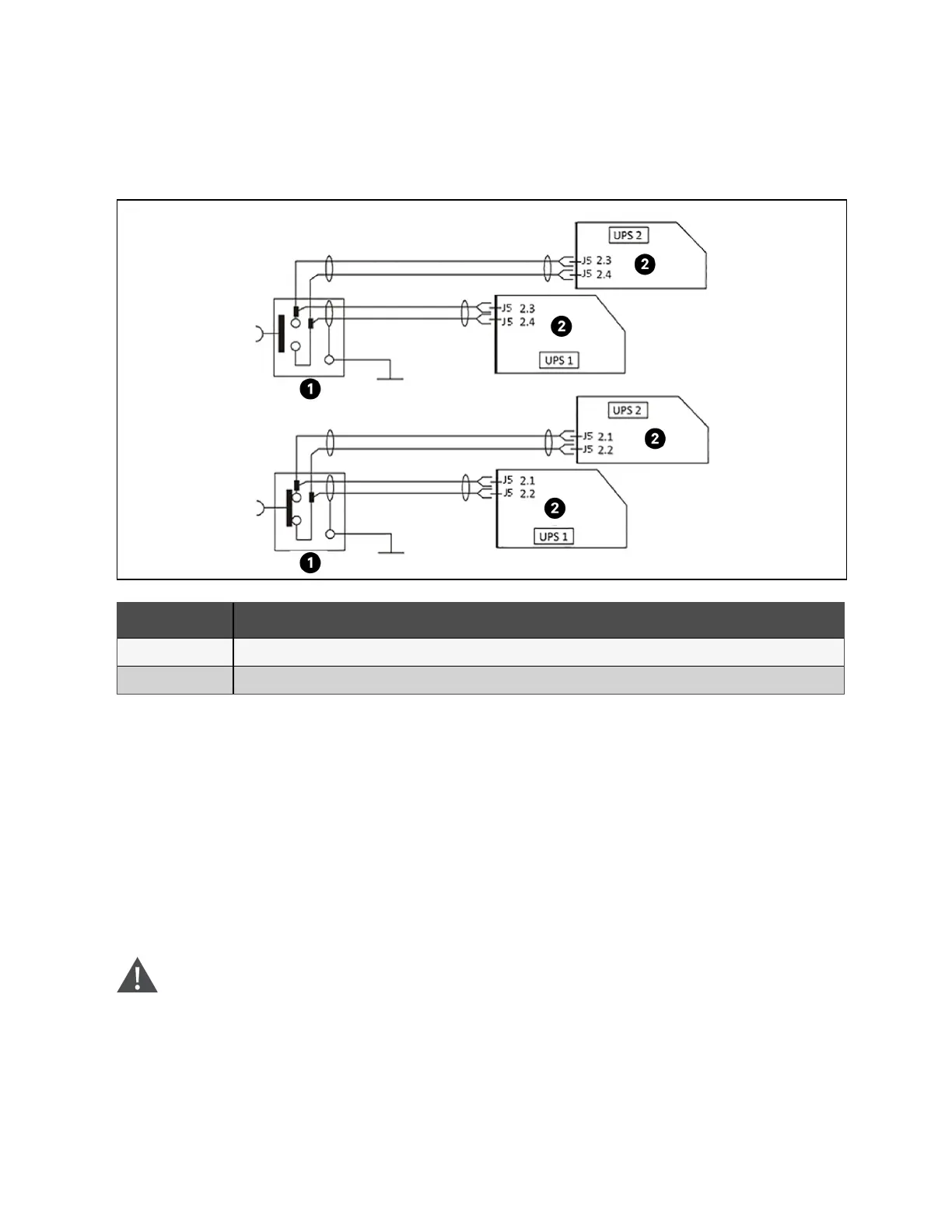
Figure 8.3 EPO Circuit Diagram
Item Description
1 EPO
2 Integrated control module
NOTE: In Figure 8.3 above, the upper one is normally open type, and the lower one is normally closed type.
8.3 Operation Procedures for Parallel System
Only one step is required at a time, and the subsequent step may only be completed when this operation step of each UPS
module has been completed.
8.3.1 Startup procedures in normal mode
These procedures are applicable to start the UPS under total power down state, which means the UPS or the maintenance
bypass switch has not supplied the load before. Make sure UPS has been completely installed and commissioned by the
engineer, and external power supply switch has been turned off.
WARNING! These procedures result in mains voltage being applied to the UPS output terminals. If any load
equipment is connected to the UPS output terminals, check with that it is safe to apply power. If the load is
not ready to receive power, disconnect the downstream load switch, and place a warning label on the
connection point of the load.
Procedure to turn ON the UPS from a fully powered down condition:
146 Proprietary and Confidential ©2023 Vertiv Group Corp. 8 Parallel System and LBS System
Vertiv™ Liebert® APM2 30 to 120 kVA Modular UPS User Manual