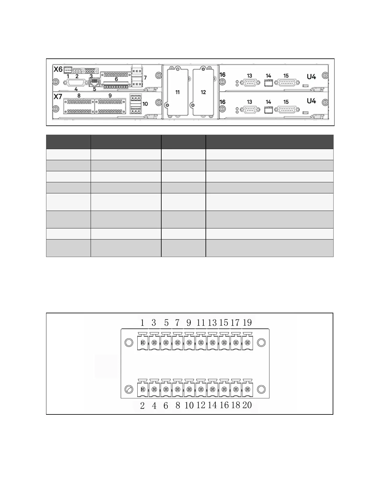
Figure 4.5 Overview of Communication Ports
Item Description Item Description
1 X6 SW1 9 X7 J2: I/O dry contact ports
2 X6 RS-485 10 X7 J3: Other programmable output dry contact port
3 X6 REPO: REPO port 11 Intellislot 1
4 X6 HMI: HMI port 12 Intellislot 2
5
X6 BATT: Battery temperature or
BMS communication port
13 U4 LBS: LBS sync signal port
6
X6 J3: BCB and I/O dry contact
ports
14 U4 SW
7 X6 J22: Backfeeding port 15 U4 parallel: Parallel communication port
8
X7 J1: BCB and I/O dry contact
ports
16 Screw (8 PCS)
4.2.2 Dry contact port X6 J3
The schematic diagram of dry contact port J3 is shown in Figure 4.6 below and the ports are described in Table 4.5 on the
facing page.
Figure 4.6 Dry Contact Port J3
42 Proprietary and Confidential ©2023 Vertiv Group Corp. 4 Electrical Installation
Vertiv™ Liebert® APM2 30 to 120 kVA Modular UPS User Manual