Service procedures for single UPS in normal mode:
1. Place the ready switch on the front panel of the power module to unready state. this will turn the red indicator
beside the ready switch ON.
2. Remove the fixing screws on both sides of the front panel of the bypass power module, and pull the module out
of the cabinet.
3. After servicing the module, put the module into the cabinet, and tighten the screws on both sides.
4. Place the ready switch to ready state. This will turn the red indicator beside the ready switch OFF and the green
indicator ON.
11.3 Key Components and Service Life of UPS
When in use, some components of UPS system will have shorter service life compared to the UPS due to abrasion. For the
safety of the UPS supply system, it is necessary to have regular inspection and replacement of these components. This
section introduces the key components of UPS and the reference years of service life. For systems under different conditions
(environment or load rate) assessment and advice by service engineers on whether to replace the device are required with
reference to the information provided in this section.
11.3.1 Life parameters and the proposed replacement time of key components
Key components in Table 11.1 below are used in the UPS system. To prevent system failures due to some device failure by
wear, it execute the regular inspection and replacement during its estimated life.
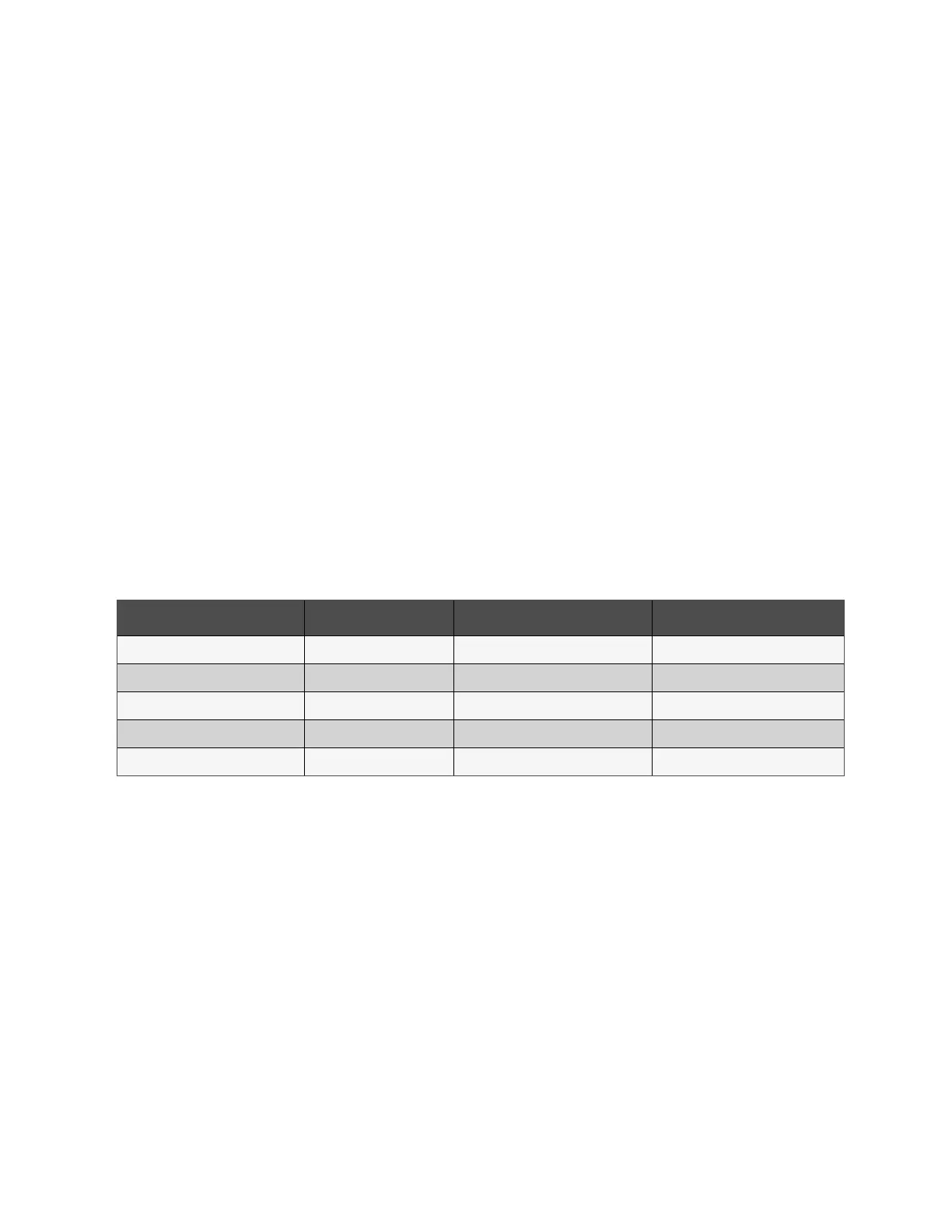
Key Components Estimated Life Proposed Replacement Time Proposed Inspection Period
Fan Not less than 7 years 5 years to 6 years 1 year
Bus Capacitor Not less than 7 years 5 years to 6 years 1 year
Air filter 1 year to 3 years 1 year to 2 years 2 months
VRLA battery (5-year life) 5 years 3 years to 4 years 6 months
VRLA battery (10-year life) 10 years 6 years to 8 years 6 months
Table 11.1 Life Parameters and the Proposed Replacement Time of Key Components
11.3.2 Replacement of air filter
NOTE: The air filters need regular inspection and replacement, which depends on the environmental conditions of the
UPS. Under normal environmental conditions, the air filters should be cleaned or replaced once every two months and
need more frequent cleaning and replacement in dusty or other unclean environments.
The UPS has air filters mounted on the rear side of the front door of the cabinet. The filters can be replaced while the UPS is
operational.
The air filters are fixed by bars on both the sides. See Figure 11.1 on the next page.
To replace the air filters:
1. Open the front door of the UPS.
2. Loosen the screws to remove one of the fixing bar while leave the other bar as it is.
3. Replace the clean air filter.
4. Reinstall the fixing bar and tighten all the fixing screws.
11 Service and Maintenance Proprietary and Confidential ©2023 Vertiv Group Corp. 169
Vertiv™ Liebert® APM2 30 to 120 kVA Modular UPS User Manual