4.2.12 Signal cable connection steps
NOTE: The power cables and signal cables should be routed respectively. The shielding coat of signal cable must be
reliably earthed.
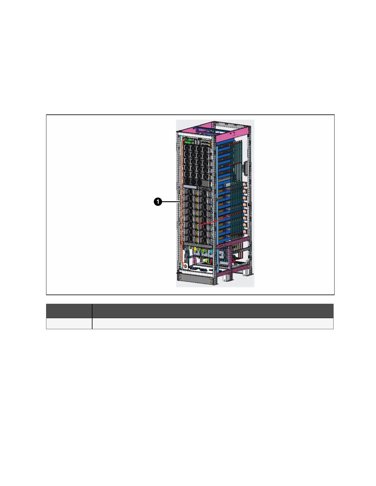
Bottom cable access is available. See Figure 4.13 below for the cabling route and then connect signal cables to corresponding
ports shown in Figure 4.5 on page42.
Figure 4.13 Signal Cables Wiring Route of 120 kVA
Item Description
1 Signal cable
4.3 Built-in Lead-acid Battery Module Installation
The installation steps of the built-in lead-acid battery module are as follows, and the relevant pictures are shown in Figure 4.14
on the next page.
1. Take out the battery module and the accessory bag, which contains the required screws, baffles and connecting
pieces.
2. Two lead-acid battery modules can be installed in each battery shelf. First install the mounting ears and brackets
on the left and right sides of the battery module. If the module is installed on the left side of the rack, install the
mounting ears on the left side and the brackets on the right side. If the module is installed on the right side of the
rack, install the mounting ear on the right side and the bracket on the left side. Use two M4 screws to fix the
mounting ear and the bracket respectively.
4 Electrical Installation Proprietary and Confidential ©2023 Vertiv Group Corp. 51
Vertiv™ Liebert® APM2 30 to 120 kVA Modular UPS User Manual