3. Push the modules into the cabinet along the guide grooves on the left and right sides of the cabinet (starting
from the bottom layer of the cabinet, and assemble them upwards in sequence).
4. Take out the connection piece from the accessory bag, fix the connection piece to the module with four M6
screws, and fix the mounting ears of the two modules to the cabinet respectively with four M6 screws.
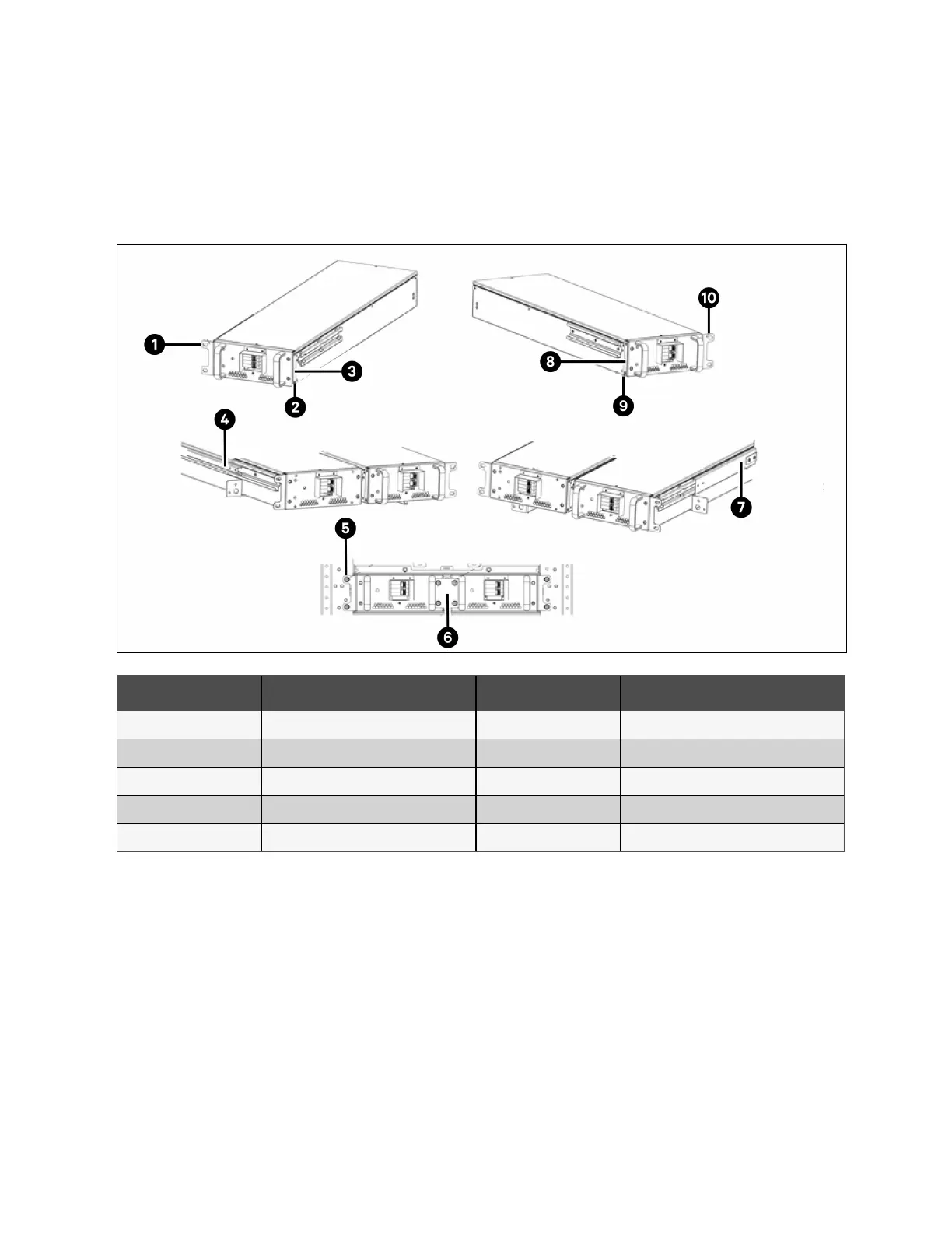
Figure 4.14 Installation Diagram of Built-in Lead-acid Battery
Item Description Item Description
1 Mounting ears 6 Connecting piece
2 M4 X 8 Screw 7 Rack rail slot
3 Bracket 8 Bracket
4 Rack rail slot 9 M4 x 8 Screw
5 M6 x 12 Screw 10 Mounting ears
52 Proprietary and Confidential ©2023 Vertiv Group Corp. 4 Electrical Installation
Vertiv™ Liebert® APM2 30 to 120 kVA Modular UPS User Manual