4.2.6 Output dry contact X7 J3 (option)
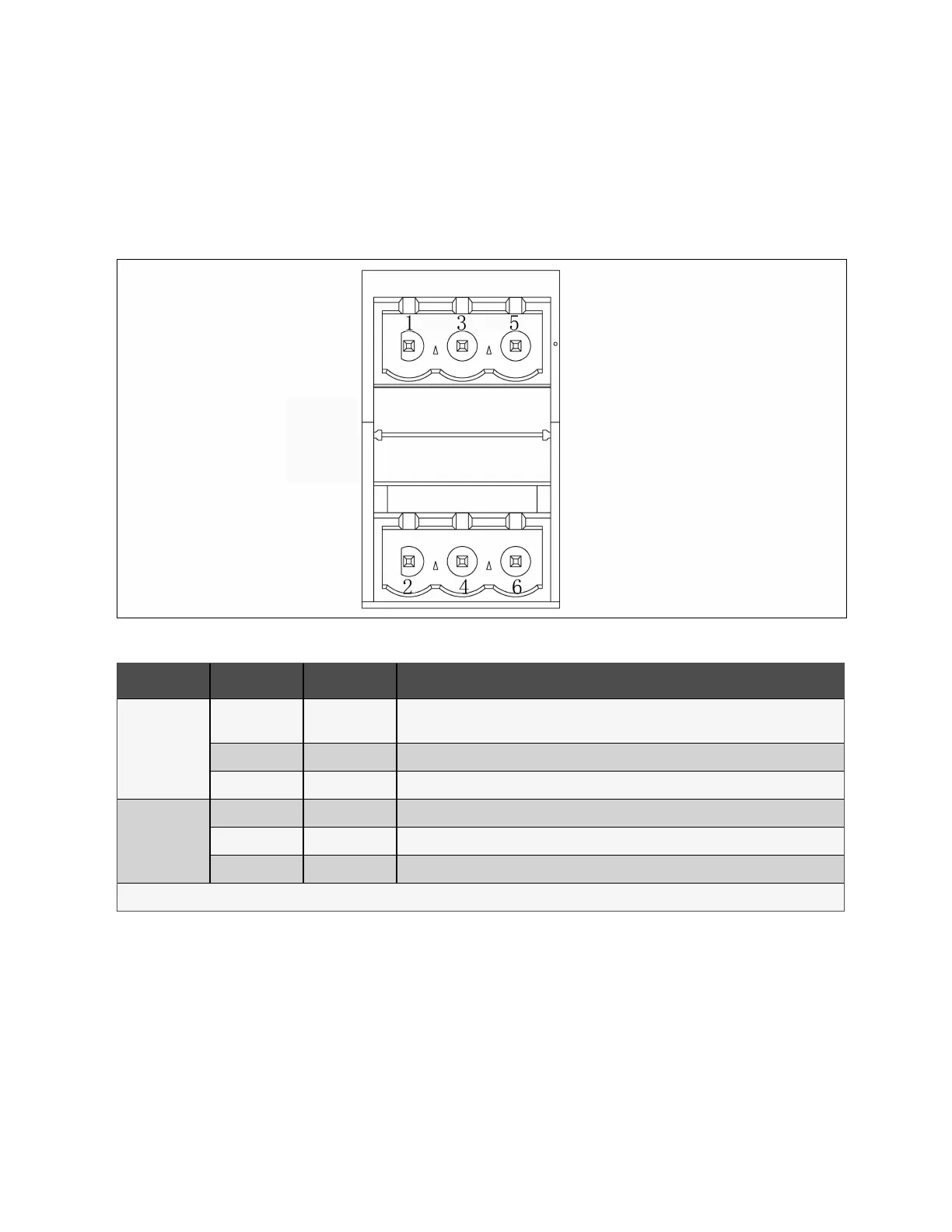
The schematic diagram of output dry contact interface J3 is shown in Figure 4.10 below and described in Table 4.9 below.
The input dry contacts of this series provide 24 V/10 mA signals, and the output dry contacts are relay contacts that can
accept 24 V/500 mA signals. BCB drive signal can provide 12 V/10 mA signal.
Figure 4.10 Dry Contact Port J3
Port Pin Name Default Signal
MBB and MIB
interlock signal
J3-1 NO
Normally open. External maintenance bypass MBB and system inverter main switch MIB
interlock signal.
J3-3 COM Common contact
J3-5 NC Normally closed
ATS transfer
enable signal
J3-2 NO Normally open. Provide remote dry contact signal to enable upstream ATS switching.
J3-4 COM Common contact
J3-6 NC Normally closed
NOTE: X7 J3 pins are programmable contacts.
Table 4.9 Description of Dry Contact Port J3
4.2.7 REPO port
The UPS consist of an EPO function that operates by either an EPO button on the touchscreen of the UPS or a remote
contact provided by the user. The REPO button has a protective cover.
Within 100 m of the communication line, use a shielded wire, and both ends of the shielded wire are grounded. If the length
exceeds 100 m, the shielded wire must go through a metal pipe.
The schematic diagram of REPO port is shown in Figure 4.11 on the next page and described in Table 4.10 on the next page.
4 Electrical Installation Proprietary and Confidential ©2023 Vertiv Group Corp. 47
Vertiv™ Liebert® APM2 30 to 120 kVA Modular UPS User Manual