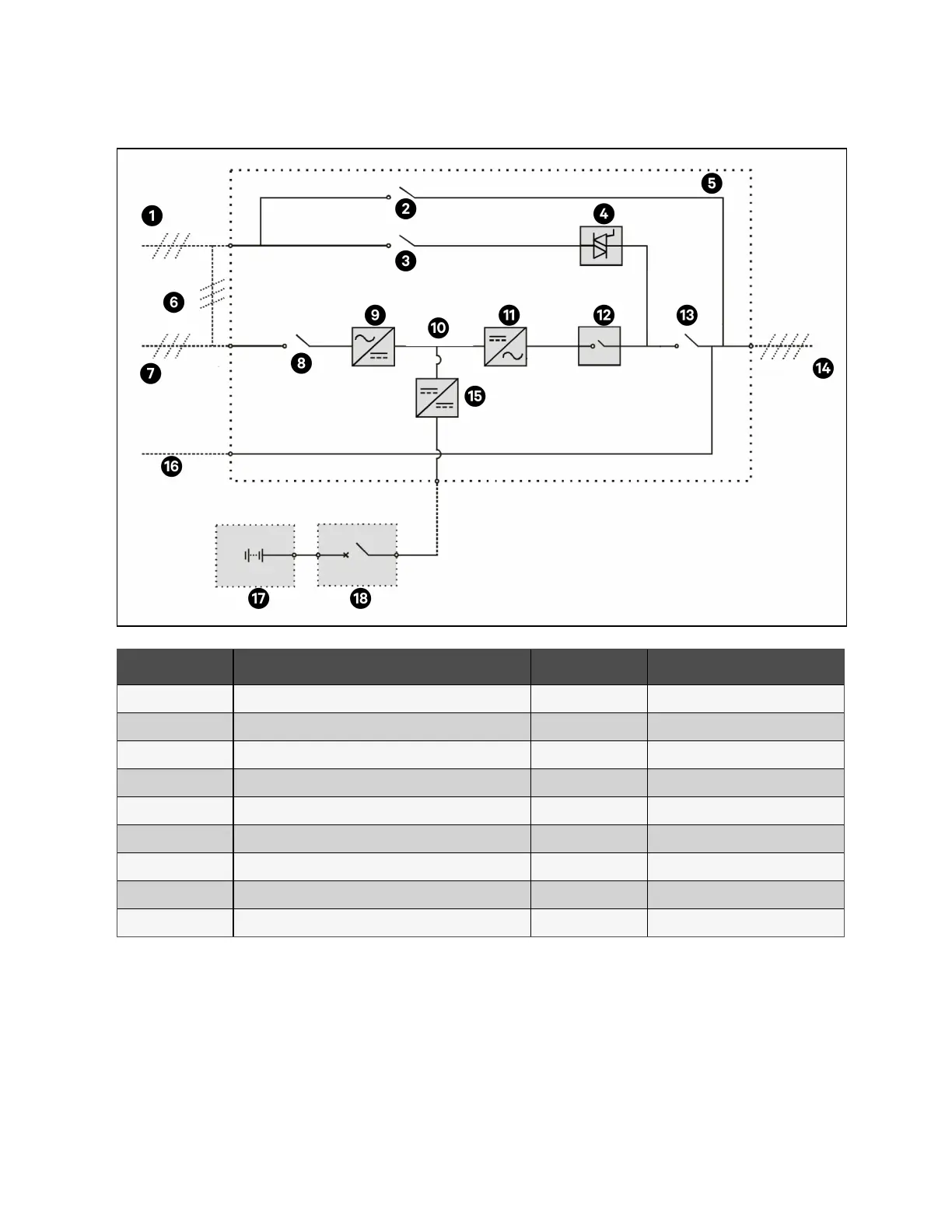
Figure 2.6 UPS Power Supply Switch Configuration Four Switches
Item Description Item Description
1 Bypass input 10 DC bus
2 Maintenance bypass switch Q3 11 Inverter
3 Bypass input switch Q2 12 Automatic Inverter switch
4 Static switch 13 Output switch Q5
5 UPS 14 UPS output
6 Shorting copper bar of input configuration 15 Battery charger/discharger
7 Mains input 16 Neutral line input
8 Rectifier input switch Q1 17 Battery
9 Rectifier 18 BCB
NOTE: The mains input and bypass input is connected to the same neutral line.
2.2.5 Battery circuit breaker (BCB)
The external battery is connected to the UPS through the BCB. The BCB cabinet is optional, and is installed near the battery.
The BCB is closed manually. The BCB has a shunt tripping coil. When the system is faulty and the BCB needed to be
disconnected, the UPS control circuit will send a signal to the shunt tripping coil to trip the BCB. It also has a magnetic trip
facility for overload protection and short circuit protection.
2 Overview Proprietary and Confidential ©2023 Vertiv Group Corp. 13
Vertiv™ Liebert® APM2 30 to 120 kVA Modular UPS User Manual