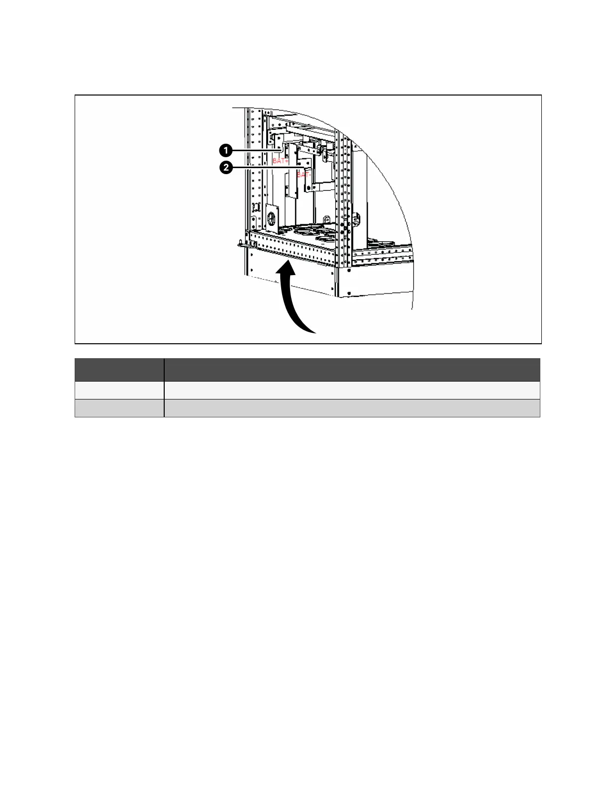
Figure 4.4 Battery Connection
Item Description
1 Battery positive connection
2 Battery negative connection
NOTE: When connecting the cables between battery terminals and BCB, the connection should begin from the battery
switch box terminal.
3. Refit all protective covers removed for cable installation.
NOTE: After connection, make sure to seal the cable entry hole on the cabinet.
4.2 Wiring of Signal Cable
4.2.1 Overview
Based on the site’s specific requirements, the Vertiv™ Liebert® APM2 UPS can require auxiliary connection to manage the
battery system (including the external battery switch) management, communicate with a personal computer, provide alarm
signal to the external devices, for the remote emergency power off (REPO) or provide bypass back feed circuit breaker signal
and parallel communication. These functions are performed through the communication box in the APM2 UPS cabinet. The
communication box provides the ports as shown in Figure 4.5 on the next page.
4 Electrical Installation Proprietary and Confidential ©2023 Vertiv Group Corp. 41
Vertiv™ Liebert® APM2 30 to 120 kVA Modular UPS User Manual