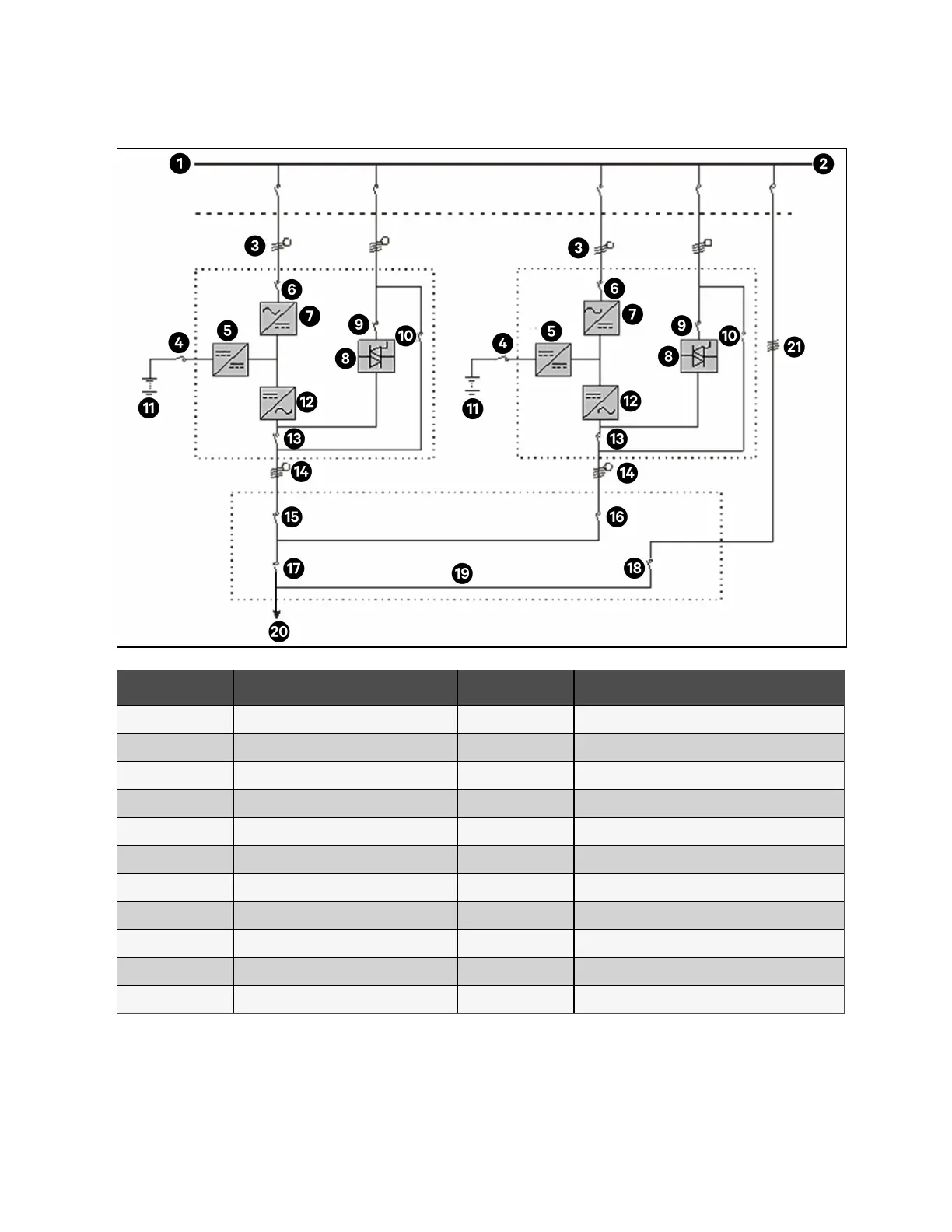
Figure 8.1 Schematic of Typical Parallel System with Common Input, Separate Batteries and Output
Item Description Item Description
1 Input power supply 12 Inverter
2 External bypass switch 13 Q5
3 Mains input L1, L2, L3, N 14 L1, L2, L3, N
4 BCB 15 QE1
5 Charger 16 QE2
6 Q1 17 QOP
7 Rectified 18 QBP
8 Static switch 19 Output distribution
9 Q2 20 To load
10 Q3 21 External maintenance bypass
11 Battery 1
NOTE: Q1, Q2, and Q5 are optional while Q3 is standard.
144 Proprietary and Confidential ©2023 Vertiv Group Corp. 8 Parallel System and LBS System
Vertiv™ Liebert® APM2 30 to 120 kVA Modular UPS User Manual