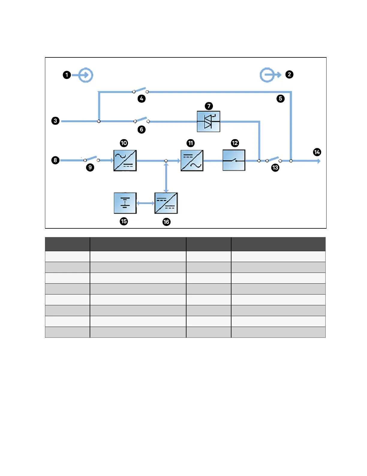
Figure 2.3 Block Diagram for Working Principle of UPS Single Module of with Four Switches
Item Description Item Description
1 Input 9 Rectifier input switch
2 Output 10 Rectifier
3 Bypass input 11 Inverter
4 Maintenance bypass switch 12 Automatic inverter switch
5 Maintenance bypass 13 Output switch
6 Bypass input switch 14 UPS output
7 Static switch 15 Battery
8 Mains input 16 Battery charger/discharger
The UPS has its own battery charger and adopts advanced temperature compensation technology to effectively improve the
battery service life. The inverter adopts 3 level T-type IGBT topology and uses advanced SVPWM control technology to
derive the stable AC voltage from the DC bus voltage.
When the mains is normal, the rectifier and inverter work together to supply the power to the load and charge the battery.
When the mains is abnormal, the rectifier stops working, and the battery supplies power to the loads through the inverter. If
the battery voltage falls to end of discharge (EOD) voltage and the mains still has not been recovered, the UPS will shutdown
(if the system uses split bypass configuration and the bypass is normal, the system will transfer to bypass). The battery EOD
voltage is preset. When the mains is abnormal, the battery maintains the UPS operation till the battery voltage is reduced to
EOD voltage and the UPS shuts down, this time is called backup time. The length of backup time depends on the battery
capacity and the loads.
8 Proprietary and Confidential ©2023 Vertiv Group Corp. 2 Overview
Vertiv™ Liebert® APM2 30 to 120 kVA Modular UPS User Manual