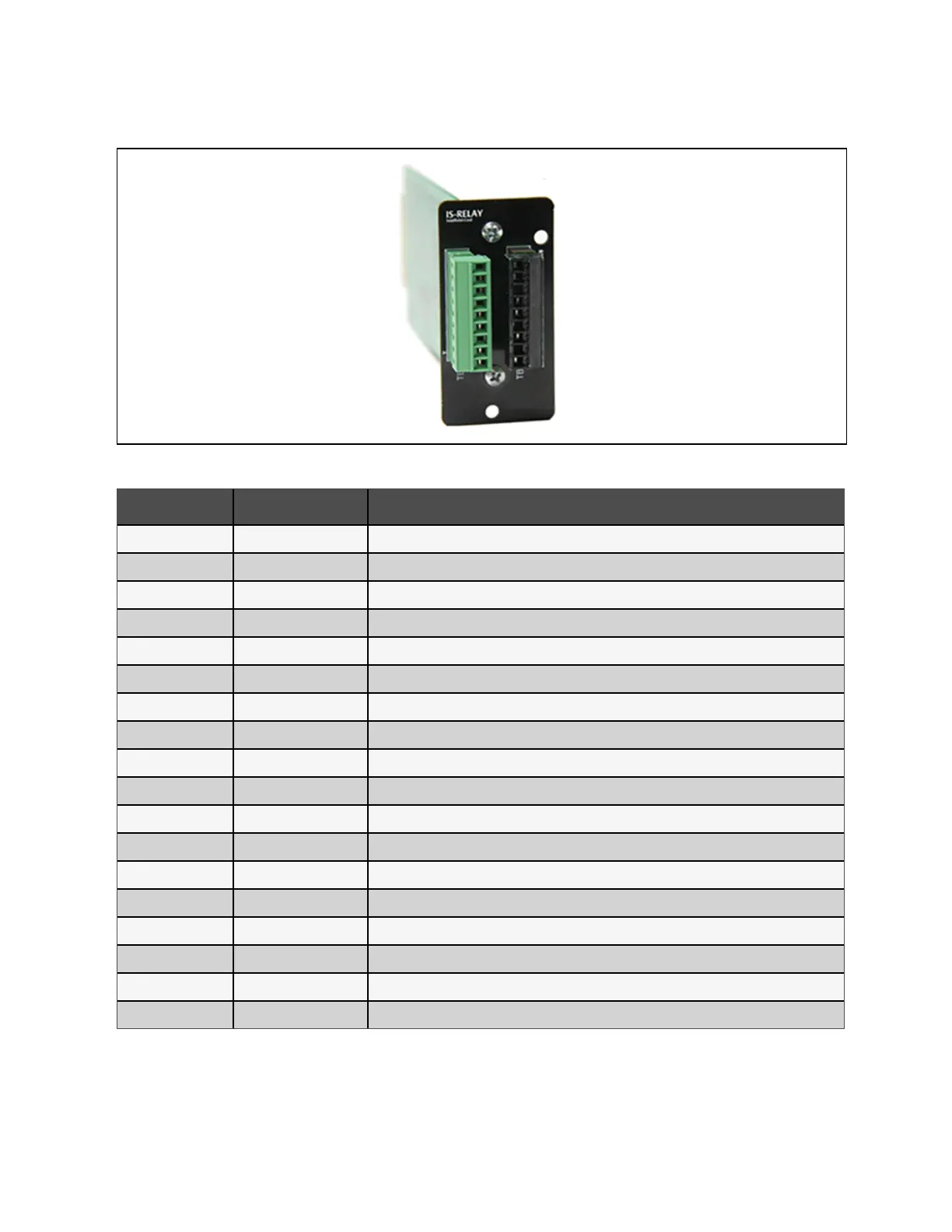
Figure 9.6 IS-Relay Card
Pin Function Operation
1 Common-Low Battery
2 Low Battery Closed if low battery point occurs
3 Low Battery Closed if battery is OK
4 Common-UPS Fault
5 UPS Fault Closed if UPS fault occurs
6 UPS Fault Closed if no UPS failure
7 Common-On Battery
8 On Battery Closed if On Battery power (Utility failure)
9 On Battery Closed if not On Battery power (Utility OK)
10 Signal Ground Future release
11 Signal Ground Future release
12 UPS Any-Mode Shutdown Future release
13 Summary Alarm Closed if no alarm conditions are present
14 Summary Alarm Closed if summary alarm occurs
15 Common-Summary Alarm
16 On UPS Closed if On UPS (inverter) power
17 On Bypass Closed if On Bypass
18 Common-On Bypass
Table 9.3 Function of UPS IS-Relay card
For more information of the IS-Relay card, refer to the Vertiv™ Liebert® IntelliSlot™IS-Relay Card User Manual in accessory.
The installation method of the IS-Relay card is the same as that of the SIC card described in SIC card on page159. Refer to
Signal cable connection steps on page51 for the cabling and routing of the signal cables.
9 Vertiv™ Liebert® APM2 Option
Configurations
Proprietary and Confidential ©2023 Vertiv Group Corp. 161
Vertiv™ Liebert® APM2 30 to 120 kVA Modular UPS User Manual