Vertiv™ | Liebert
®
STS2
™
100-1000A, 50/60Hz User Manual | Rev. 12 | 11/2017 101
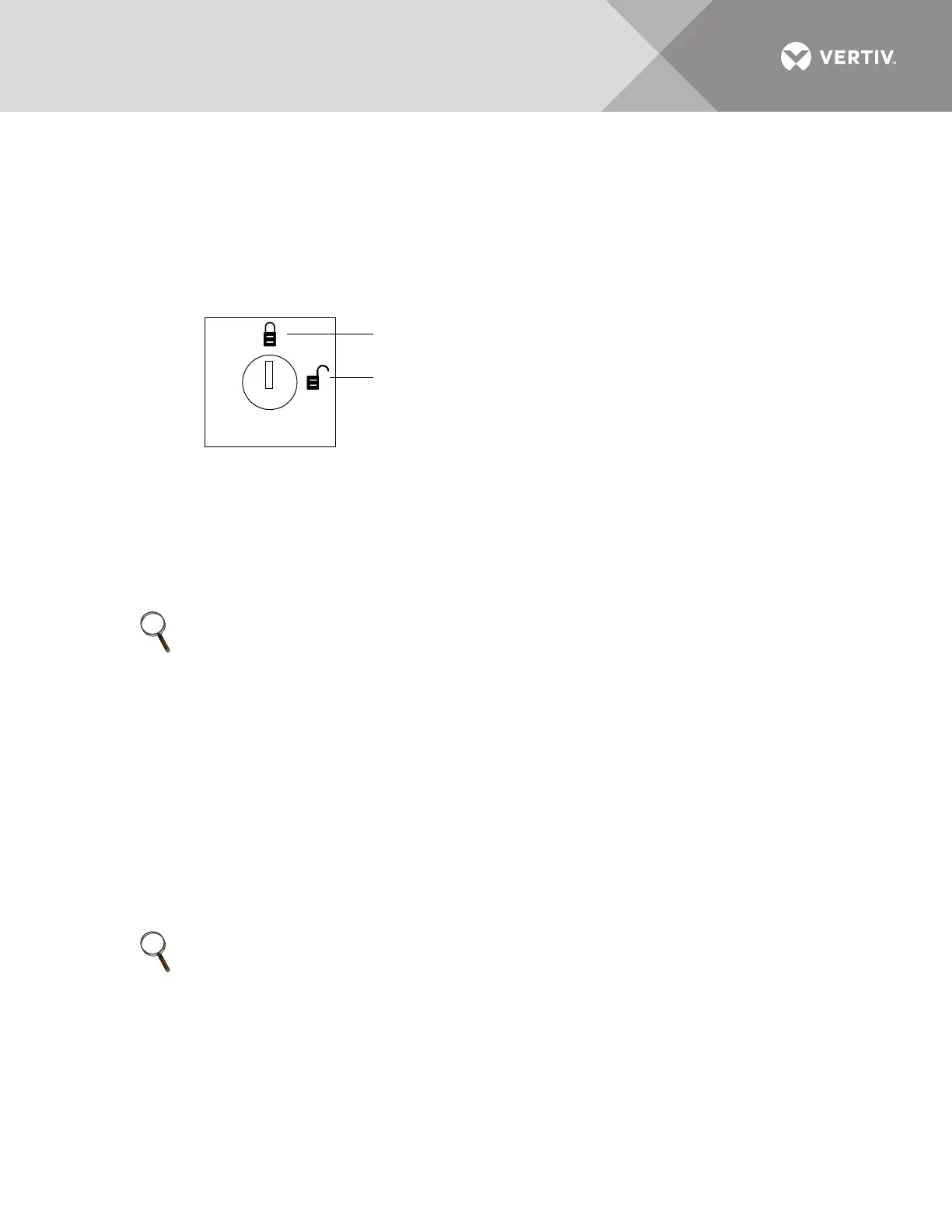
14.1.4 Key Lockout Switch
An optional key lockout switch for the Liebert STS2 enables or disables all push button inputs, except for the
alarm silence button. The key lockout switch is mounted on the front of the unit. See Figures 7 to 9 for the key
lockout switch location on each unit.
• To disable the buttons, turn the key to the top of the switch, toward the closed padlock icon.
• To enable all of the buttons, except the alarm silence, turn the key to the horizontal position, toward the open padlock icon.
Figure 58 Key lockout switch.
14.2 Operations
This section discusses the system startup, shutdown and bypass procedures for the LED-based Liebert STS2.
If your unit has an LCD touchscreen, see 10.0 - OPERATING INSTRUCTIONS FOR THE TOUCHSCREEN
INTERFACE for instructions these procedures.
14.2.1 Normal System Startup
This section provides instructions to start up the Liebert STS2. The LED’s provide the basic information required
to ensure proper operation. To monitor metering data, use a PC terminal.
1. Ensure that all Liebert STS2 breakers—CB1, CB2, CB3A (if supplied), CB3, CB4, and CB5—are in the OFF (open) position.
a. Ensure that the key interlocks for CB1 and CB2 have their bolts retracted.
b. Ensure that the key interlocks for CB4 and CB5 have their bolts extended, thus preventing CB4 or CB5 from being
turned ON.
c. Ensure that the circuit breakers respective LED’s are Off.
2. Source/input power should be applied to both Liebert STS2 inputs.
Check that the green LED’s for each source are lit.
3. Verify that nominal input voltages are applied to both inputs (Source 1 and Source 2).
Check that the green LED’s monitoring the sources are lit indicating the sources are within acceptable tolerances.
4. Close CB1.
The green LED monitoring CB1 turns On.
5. Close CB2.
The green LED for CB2 turns On.
6. Verify that the preferred source LED (green) (LED_PREFx) is lit for the source that you want the switch to be using.
7. Verify that the green LED for the corresponding SCR (Liebert STS1 or Liebert STS2) is lit, indicating that the SCR is closed.
NOTE
If your Liebert STS2 is connected to a PDU with a Wye configuration, enable the Wye Output Transformer before
starting the system. This configuration can be done from a PC terminal. Refer to 12.1 - Using the RS-232 Port for
instructions.
NOTE
For redundant output switch units, CB3 descriptions apply to CB3 and CB3A.
Changes disabled
Changes enabled