Vertiv™ | Liebert
®
STS2
™
100-1000A, 50/60Hz User Manual | Rev. 12 | 11/2017 24
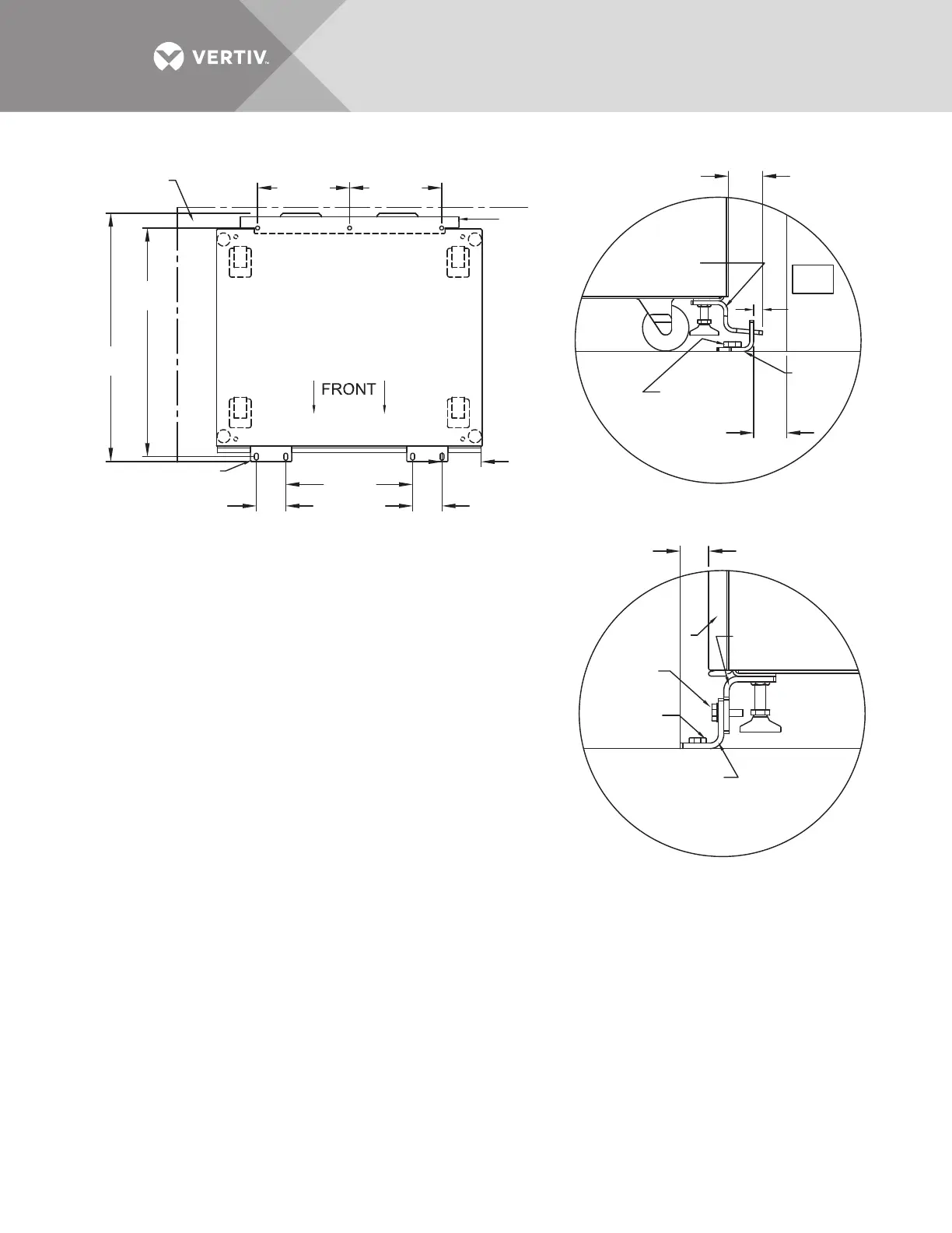
Figure 11 Seismic anchor drawing: 400 – 600 amp Liebert STS2
PS211405
Rev. 1
See Note 7
for spacing
Rear Floor
Bracket
See Note 2
for spacing
Rear Cabinet
Base Bracket
Rear Floor
Bracket
Front Floor
Bracket
Front Floor
Bracket
Floor Line
Front Door
of Cabinet
Front Cabinet
Base Bracket
Floor Anchor
Hardware
(Field-Supplied)
Hardware
Supplied
Floor Anchor
Hardware
(Field-Supplied)
13.2"
(335mm)
32.75"
(832mm)
35.72"
(907mm)
4.2"
(107mm)
18.2"
(462mm)
13.2"
(335mm)
Back Wall
Back
Wall
Side Wall
4.2"
(107mm)
5.75"
(146mm)
3/4"
(19mm)
2.26"
(57.5mm)
1.364"
(34.6mm)
Front
TOP
System Seismic Anchoring, Figure 1
Figure 2
Figure 3
Floor Line
1/2"
(12.5mm)
Approx.
NOTES
1. Recommended floor anchor: 1/2" ITW Ramset/Red Head self-drilling
anchor; ICBO #ER-1372 or equivalent (not supplied). Follow
manufacturer's instructions.
2. Position rear floor brackets on floor at least 0.75" (19mm) from back
wall. Mark location and drill holes (Figure 1) to a minimum depth
of 4.12" (104.7mm) into the concrete.
3. Install rear cabinet base bracket (Figure 2) to existing holes on the
underside of the unit with tabs facing the back wall. Use supplied
hardware and torque to 365 lb./in. (41.2Nm). Loosen leveling bolt
locking nut and tighten after the bracket is secured.
4. Install the front cabinet base to existing holes on the underside of
the unit with the bent flange facing front. Use the supplied hardware
and torque to 365 lb./in. (41.2Nm). Loosen leveling bolt locking nut and
tighten after the bracket is secured.
5. Move the cabinet into position with the rear tabs into the slots of the
floor bracket. The tabs must extend at least 1/2" (12.7mm) through
the floor bracket (Figure 2). Then attach the front floor brackets to the
front cabinet base bracket, but do not fully tighten the hardware.
6. Mark the hole locations and remove the brackets. Drill and install the floor
brackets. The unit's door can be removed for better access. Reinstall the
front floor brackets to the front cabinet brackets with the supplied hardware
and torque to 235 lb./in. 26.5Nm); see Figure 3.
7. If side walls are present, 5" (127mm) minimum distance from either side
wall is required.
8. Rear and front floor brackets and the rear and front cabinet base brackets
are 1010 steel and approximately 1/4" (6.4mm) thick.