Vertiv™ | Liebert
®
STS2
™
100-1000A, 50/60Hz User Manual | Rev. 12 | 11/2017 108
15.2 System Components
All Liebert STS2 models provide two static transfer switches within one enclosure, with the ability to transfer
between two input sources to a single output.
All Liebert STS2s are configured with either an LCD Color Graphical Interface touchscreen display or LED’s for
monitoring and configuring the unit.
This section lists the common components and the differences for both types of units.
15.2.1 Frame and Enclosure
The complete Liebert STS2 is housed in a freestanding enclosure. The cabinet is a NEMA type 1 enclosure and
meets IP20 requirements. The cabinet is structurally designed to handle lifting from the base. The frame is
designed to accommodate floor stands.
The distributed floor weight for Liebert STS2 is less than 150 lb./sq. ft. (660kg/m²).
The required service access is only from the front of the unit.
The Liebert STS2 can be tipped 15° in any direction without falling over.
15.2.2 Casters, Leveling and Seismic Anchoring
The frame includes heavy-duty swivel casters for ease of installation, plus permanent leveling feet for final
installation.
The unit also can be fastened to the floor using optional seismic anchors to meet seismic Zone 4 requirements.
See 4.0 - Locating the Liebert STS2 and Figures 10 through 12 for instructions and details for installing
seismic anchoring.
15.2.3 Cooling
The Liebert STS2 100 – 600A units utilize convection air cooling for the enclosure with forced air cooling of the
heat sinks. The 800-1000A units are fan cooled using low-velocity fans to minimize audible noise. All fans are
redundant so that a single fan failure cannot cause temperatures to increase beyond acceptable limits.
Air intake is through screened protective openings in the front of the unit. A standard furnace filter is installed
behind the openings.
By opening the front door, the filter can be changed easily without exposing personnel to high voltage.
The size of the filter is 1 in. x 25 in. x 25 in. (2.54 cm x 63.5 cm x 63.5 cm).
The air exhaust is through the top of the unit.
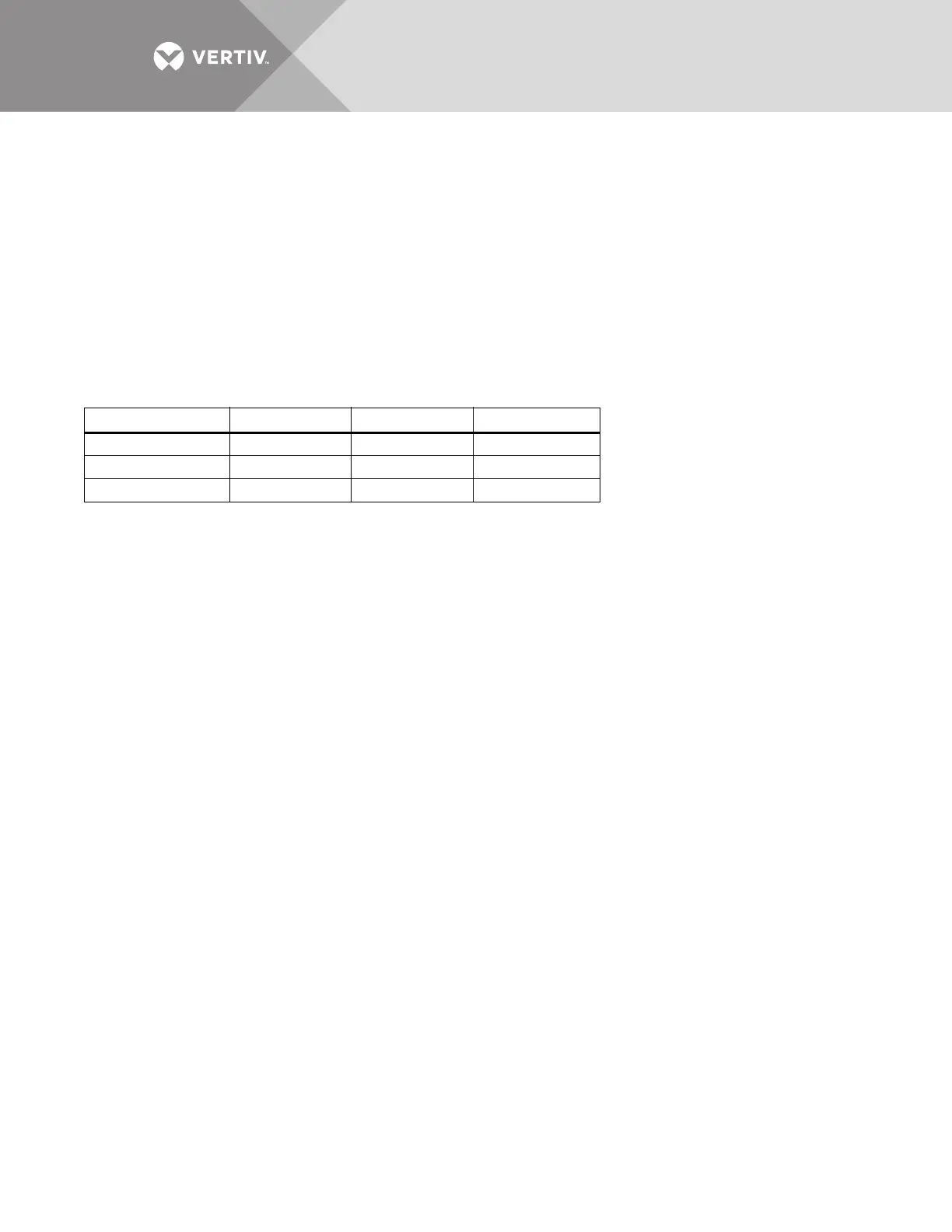
Table 16 Frame sizes
Rating Width, in. (mm) Depth, in. (mm) Height, in. (mm)
100 – 250A 3-pole 30 (762) 32 (813) 76.77 (1950)
400 – 600A 3-pole 38 (965) 32 (813) 76.77 (1950)
800 – 1000A 3-pole 84 (2134) 32 (813) 76.77 (1950)