Vertiv™ | Liebert
®
STS2
™
100-1000A, 50/60Hz User Manual | Rev. 12 | 11/2017 91
13.8.1 Configuring the Input Contact Isolator Settings
The Input Contact Isolator (ICI) is an optional, eight-channel input board for up to eight external user alarm or
message inputs to be routed to the Liebert STS2’s alarm network. If the Transfer Inhibit option is supplied, the ICI
will accommodate up to seven external user alarm or message inputs.
The contact is set to normally open. When a contact closes or opens, an event is triggered. See 6.4 - Input
Contact Isolator Board for more information on the ICI.
The Input Contact Isolator options are configured through the Input Contact Isolator dialog box, which is
accessed from the Comm Options dialog box. The Input Contact Isolator dialog box contains eight choices to
match the eight channel input board. You can label each button to identify the event associated with the contact.
When the dialog box is accessed, each button flashes to display the Input Contact Isolator number and the user
entered label. This label also appears in the Display Panel when an event related to an Input Isolator Connector is
triggered.
The Input Contact Isolator dialog box allows you to:
• Label the input contact assignments for your setup.
• Set the delay for an external event triggering an alarm.
• Review the isolator contact assignments, once the labels are entered.
The delay allows you to set the number of seconds which a condition needs to persist to trigger an alarm.
These input alarms can also be configured to activate a programmable relay output, which is discussed in
Configuring the Programmable Relay Board Settings on page 92.
When the Transfer Inhibit option is supplied, connect a N.O. dry contact (customer-supplied) to Input Contact 8
(Pins 15 and 16). When the customer contact closes, transfers will be inhibited as long as the contact remains
closed. Input Contact 8 is factory-set so no setup is required. The Transfer Inhibit option prevents Input Contact
8 from being used for any other input.
To configure the Input Contact Isolator relays:
1. Select INPUT CONTACT ISOLATOR from the Comm Options menu.
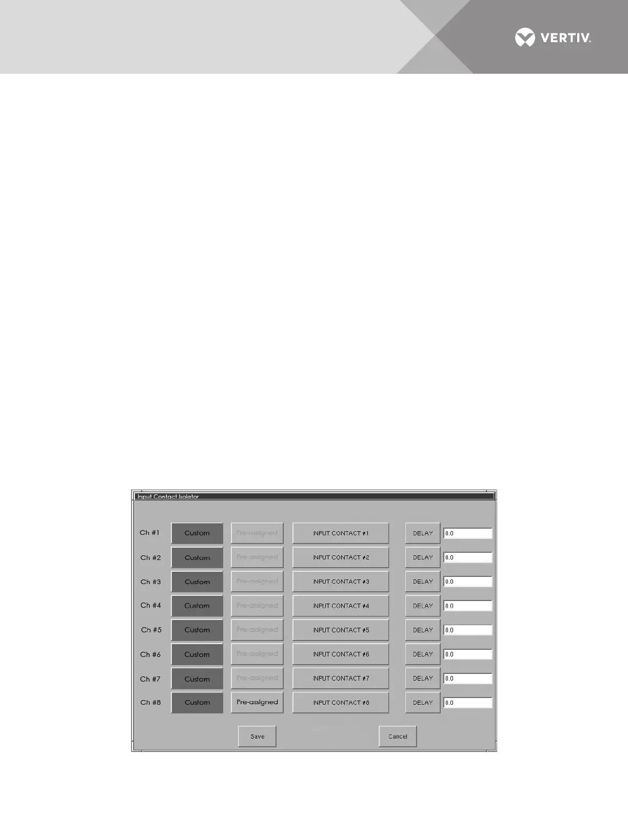
The Input Contact Isolator dialog box is displayed.
Figure 52 Input contact isolator dialog box