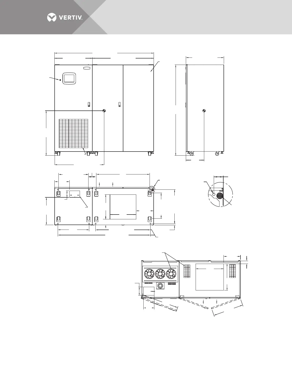
84" (2134mm)
52" (1321mm)
Breaker
Cabinet
Key
Lockout
Switch
45.2" (1149mm)
Caster Centers
12mm
Centers
29"
(736mm)
12mm Diameter
Mounting Hole
(4 Typically)
See Note 9
12mm
Centers
21.6"
(548mm)
Caster
Centers
2.75"
(69.8mm)
Typical
NOTES
1. 18" (457mm) clearance above unit is required
for air exhaust.
2. Clearance of 36" (914mm) is required in the
front only for installation and service access.
3. Heat output: 13,780 BTU/Hr (4.03kW) maximum
for 800A switch.
17,390 BTU/Hr (5.09kW) maximum
for 1000A switch.
4. Weight: 2500 lb. (1134kg)
5. Unit bottom is structurally adequate for
forklift handling.
6. Keep cabinet within 15 degrees of vertical.
7. Color: Black gray matte
8. Open door to replace air filter, disposable
type 1"x25"x25"
(25.4 x 635 x 635mm).
9. Threaded mounting holes (see Detail A) are
provided for seismic anchoring or floor stand.
Mounting bolts must be threaded into
the unit from underneath the unit base.
If a floor stand is used, the casters must
rest on the floor stand to support the unit's weight.
10. 500 CFM (236 L/S) per exhaust fan.
32" (813mm)
32.1" (815mm)
77"
(1956mm)
.98"
(25mm), Ref.
4.8" (122mm)
41.9" (1064mm)
6.7"
(171mm)
20.9"
(530mm)
78.4" (1992mm)
46.4" (1180mm)
26.5"
(673mm)
22.1"
(560mm)
14.9"
(378mm)
7.1"
(180mm)
9.1"
(230mm)
2.4"
(61mm)
22.4"
(570mm)
14.2"
(361mm)
23.6"
(600mm)
25.8"
(655mm) Typical
31.9"
(810mm)
5.5"
(139mm)
15.4"
(391mm)
Center
of
Gravity
Center
of
Gravity
Air Intake Area
Do Not Block
Air Filter
FRONT
FRONT
FRONT
SIDE
TOP
PS211801
Rev. 4
BOTTOM
DETAIL A
Front of Unit Shown
Without Side Panel
See
Detail A
Power Cable
Bottom Entry
Area
Control Cable
Bottom Entry Area
Power Cable
Top Entry Area
Maximum Door
Swing 180º
Air Exhaust,
Typical
Leveler
38"
(965mm)
23.3"
(592mm)
12.7"
(323mm)
5.5"
(140mm)
25.3" (642mm)
8.7"
(220mm)
Control Cable
Top Entry Area