Vertiv™ | Liebert
®
STS2
™
100-1000A, 50/60Hz User Manual | Rev. 12 | 11/2017 10
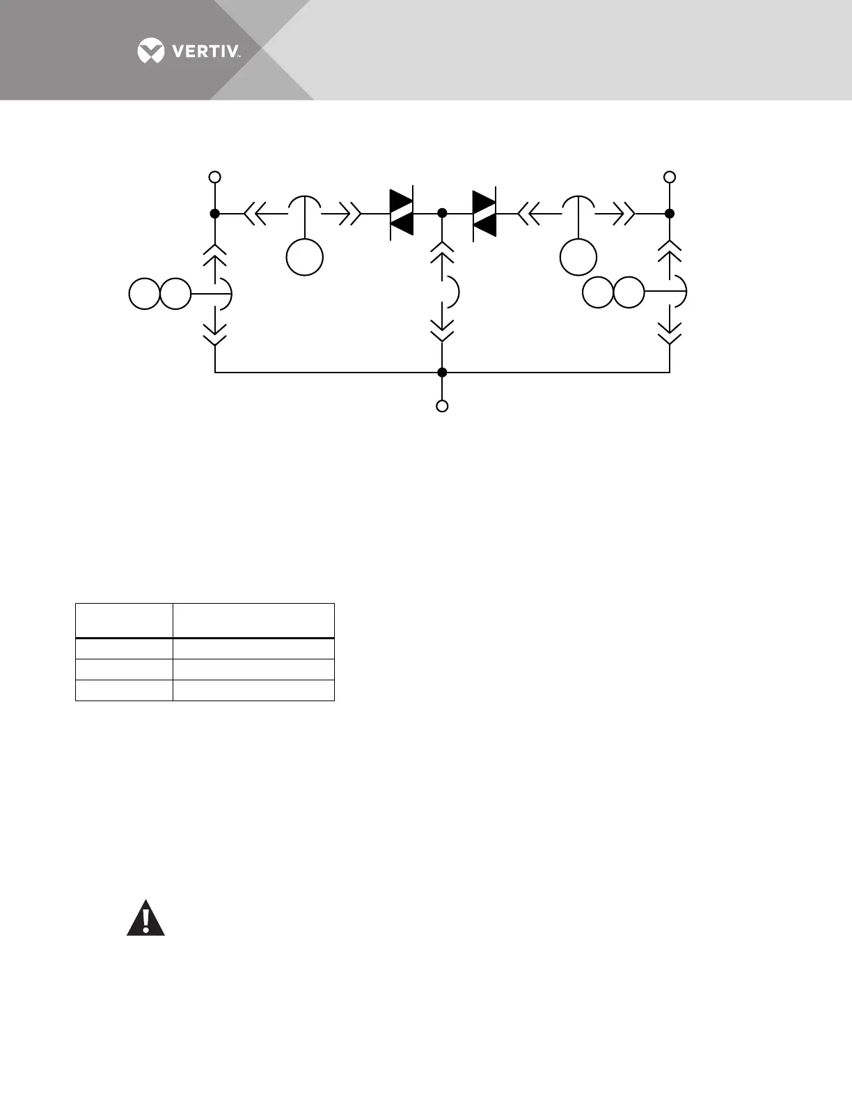
Figure 2 Typical static transfer switch one-line diagram
The input and output power wire size should be based on the upstream overcurrent protection device, observing
the NEC and local codes.
The molded case switches contained in the Liebert STS2 are typically non-automatic circuit breakers that rely
on the upstream and/or load overcurrent protection. Upstream overcurrent protection should be rated equal to
or less than the rating of the Liebert STS2 molded case switches.
The Liebert STS2 input and output power and ground and neutral bus bars accommodate a wide range of wire
sizes. The Liebert STS2 busbars accommodate standard two-hole lugs.
5.2 System Grounding
Equipment grounding — Grounding is primarily for equipment and personnel safety, although proper grounding
also enhances equipment performance.
All input and output power feeds must include an equipment grounding means as required by the NEC and local
codes.
An insulated equipment ground conductor is recommended to run with each input and output power feed. The
equipment ground conductors should be at least the minimum size conductor per the NEC based on the
upstream overcurrent protection device.
Table 2 Input/output conduit plate specifications
Rating
Maximum Number
and Size
100-250A 6 — 3" conduit
400-600A 9 — 4" conduit
800-1000A 12 — 4" conduits
WARNING
If conduit is used as a grounding means, adequate electrical continuity must be maintained at all conduit
connections. The use of isolating bushings with a metal conduit can be a safety hazard and is not
recommended.
K1 K3
K2 K3
K1 K2
OUTPUT
CB4 CB5CB3
SOURCE 1 SOURCE 2
STS1 STS2
CB1
CB2