Vertiv™ | Liebert
®
STS2
™
100-1000A, 50/60Hz User Manual | Rev. 12 | 11/2017 40
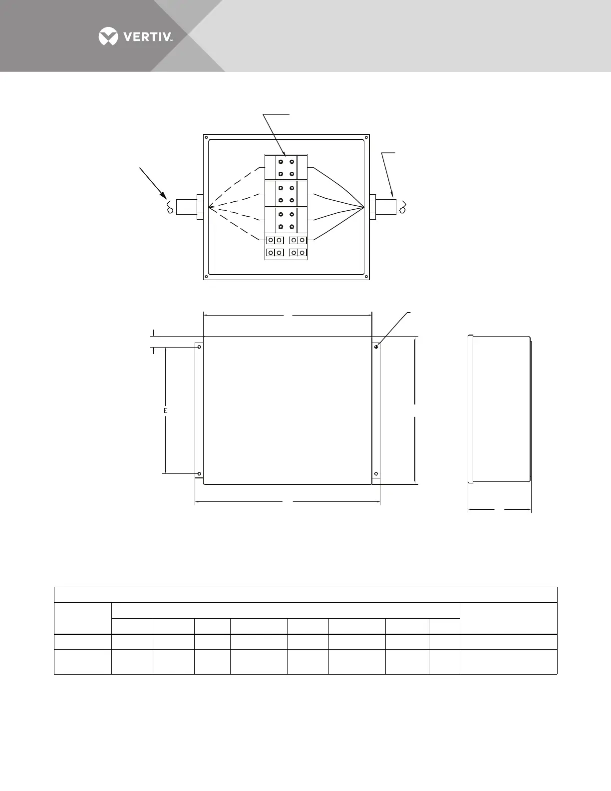
Figure 27 Outline drawing for input junction box
Input Junction Box
Rating
Dimensions, Inches (mm)
Wire Size RangeABC D E F GH
100A 16 (406) 14 (356) 6 (152) 17-1/2 (445) 12 (305) 16-3/4 (426) 5/16 (8) 1 (25) #6 AWG to #2/0 AWG
250A - 600A 16 (406) 30 (762) 6 (152) 33 (830) 10 (254) 32 (813) 7/16 (11) 3 (76)
(2) #6 AWG to (2)
500 kcmil
PS211005
Rev. 0
A
B
C
G
D
B
H
A
C
Power Terminal Block
Recommended location for
customer connection of
input power raceway (by
others); 3-phase, 3-wire
plus ground
Location of
factory-supplied
input power
cable assembly
INPUT JUNCTION BOX
G diameter
hole
1. Two junction boxes are supplied; one for each output.
2. Cable(s) to connect the junction box to the input busbars
are factory supplied. See electrical field connections
drawing for location.
3. Parallel cables are used on 400A and 600A units.