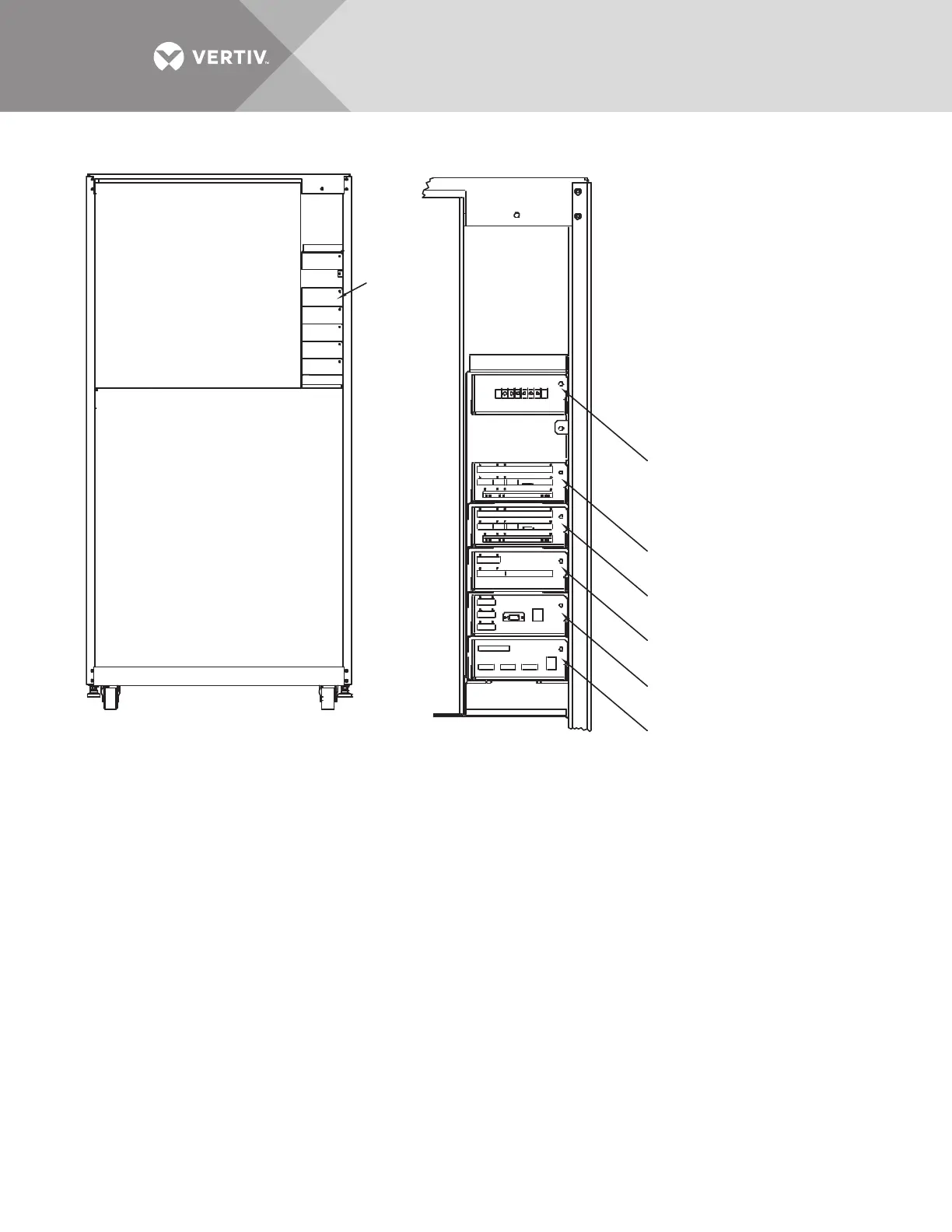
EasyManua.ls Logo

Vertiv Liebert STS2/PDU - Figure 19 Control Connection Location Diagram: 100 - 600 Amp Liebert STS2

Vertiv Liebert STS2/PDU
144 pages
Print Icon
To Next Page IconTo Next Page
To Previous Page IconTo Previous Page
Loading...
Vertiv | Liebert
®
STS2
100-1000A, 50/60Hz User Manual | Rev. 12 | 11/2017 32
Figure 19 Control connection location diagram: 100 – 600 amp Liebert STS2
CONTROL WIRING
Front; Door Not Shown
PS213000
Rev. 2
NOTES
1. Typical options are shown.
2. A maximum of two programmable
relay boards can be used
Remote Source
Select (Option)
See Option
Location
Detail
Programmable Relay
Board (Option); See Note 2
Programmable Relay
Board (Option); See Note 2
Input Contact Isolator Board
(Option) or Programmable Relay
Board (Option); See Note 2
Comms Board for Liebert
SiteScan
Network Interface
Card (Option)
OPTION LOCATION DETAIL

Table of Contents

Related product manuals