P99
P66
PS213001
Rev. 3
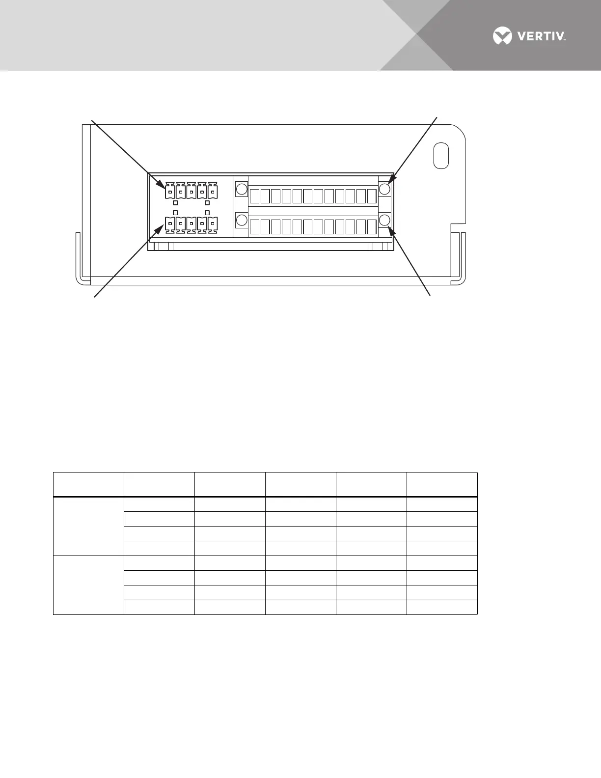
J71
J72
PROGRAMMABLE RELAY BOARD
NOTES
1. Customer control wiring connection points are Terminal
Blocks 1 through 12.
2. Programmable relay board option includes eight signal
channels with one Form-C dry contact per channel. See
table. C = Common; NC = Normally Closed;
NO = Normally Open
3. Refer to accompanying text to configure the programmable
relay board option.
4. All control wiring (by others) must be run separately from
power wiring. Control wiring runs should not be combined
in the same conduit.
5. Refer to static switch control connection diagram
for location of program relay board option.
6. Contact ratings: 1A @ 30VDC, 400mA @ 125VAC.
7. Maximum cable length 500 ft. (152m) with #16AWG
flexible stranded cable.
8. All wiring must be in accordance with national and
local electrical codes.
132465798101211
132465798101211