NOTES:
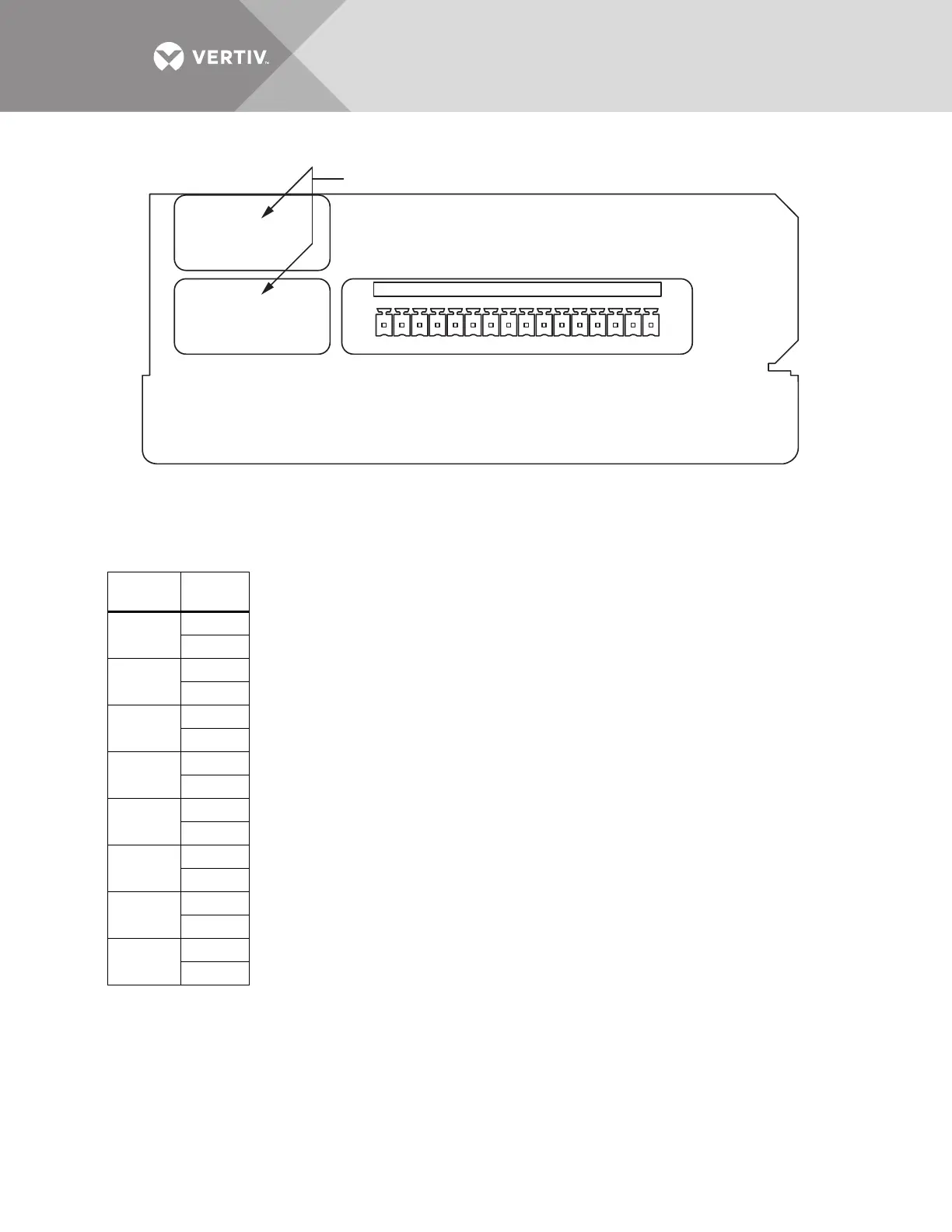
1. Customer control wiring connection points are Terminals 1 through 16
(see Table J51).
2. Customer-provided, normally open, dry contacts for user alarm messages.
3. Refer to installation, operation and maintenance manual for configuring the Input Contact
Isolator board option.
4. All control wiring (by others) must be run separate from power wiring. Control wiring runs
should not be combined in the same conduit.
5. Refer to static transfer switch control connection diagram (Figure 19 or 20) for location of Input
Contact Isolator board option.
6. Signal voltage: 100mA @ 12VDC.
7. Maximum cable length 500 ft. (152 m) with #16 AWG flexible, stranded cable.
8. All wiring must be in accordance with national and local electrical codes.
9. When the Transfer Inhibit option is supplied, connect a N.O. dry contact (customer-supplied) to
Input Contact 8 (Pins 15 and 16). When the customer contact closes, transfers will be inhibited
as long as the contact remains closed. Input Contact 8 is factory-set so no setup is required.
The Transfer Inhibit option prevents Input Contact 8 from being used for any other input.
Table J51
Input
Contact Pin No.
1
1
2
2
3
4
3
5
6
4
7
8
5
9
10
6
11
12
7
13
14
8
15
16