Vertiv™ | Liebert
®
STS2
™
100-1000A, 50/60Hz User Manual | Rev. 12 | 11/2017 29
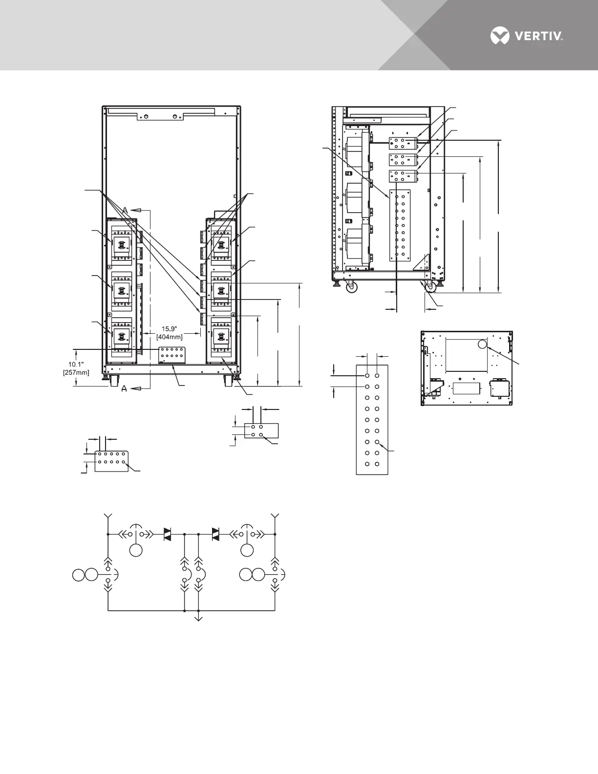
Figure 16 Electrical field connections drawing: 400 – 600 amp Liebert STS2 with dual output breakers
GROUND BUS
NEUTRAL BUS
Right Side
Neutral
Bus
Ground
Bus
INPUT/OUTPUT BUS
Right Side
Source 1 Source 2
SYSTEM OUTPUT
One-Line Diagram
FRONT
(Panels Removed)
CB1
CB4
CB3
CB3A
CB2
CB5
K1
K1
K2
K2
K3
K3
NOTES
1. Top and bottom cable entry available through
removable access plates.
Remove, punch to suit conduit size and replace.
2. Control wiring and power wiring must be run in
separate conduit. Output cables should be run
in a separate conduit from input cables.
3. Aluminum and copper-clad aluminum cables
are not recommended.
4. All wiring must be in accordance with national
and local electrical codes.
5. Hardware kit is supplied for input, output, neutral
and ground cable connections. Kit includes
1/2" bolts, washers and nuts for connecting
cables to the busbars.
6. The torque requirement for 1/2" - 13 PEM nuts
is 428 in./lb (48Nm).
1.3" (33mm)
Typical
1.75"
(44mm)
1.75"
(44mm)
1.75"
(44mm)
1.97" (50mm)
1.75"
(44mm)
Ø 0.51"
(13mm) Typical
1/2" - 13
PEM Nut
1/2" - 13
PEM Nut
Source 2 Input
Ø A, Ø B, Ø C
Source 1 Input Ø A
Source 1 Input Ø B
Source 1 Input Ø C
Source 2
Output
Ø A, Ø B, Ø C
CB2
CB5
28.3"
(719mm)
23.8"
(605mm)
7.8"
(198mm)
7.6"
(193mm)
19.3"
(490mm)
CB3
CB3A
CB4
CB1
32.9"
(836mm)
41.9"
(1064mm)
37.4"
(950mm)
See Detail A
Ø 3.5"
(89mm)
Hole
DETAIL A
Top View Looking Down
SECTION A-A
Side View
Front
PS212401
Rev. 4