1.75"
(44.4mm)
1.75"
(44.4mm)
1.75"
(44.4mm)
1/2" - 13
PEM Nut
1/2" - 13
PEM Nut
1.77" (45mm)
Typ.
1.75"
(44mm)
Typ.
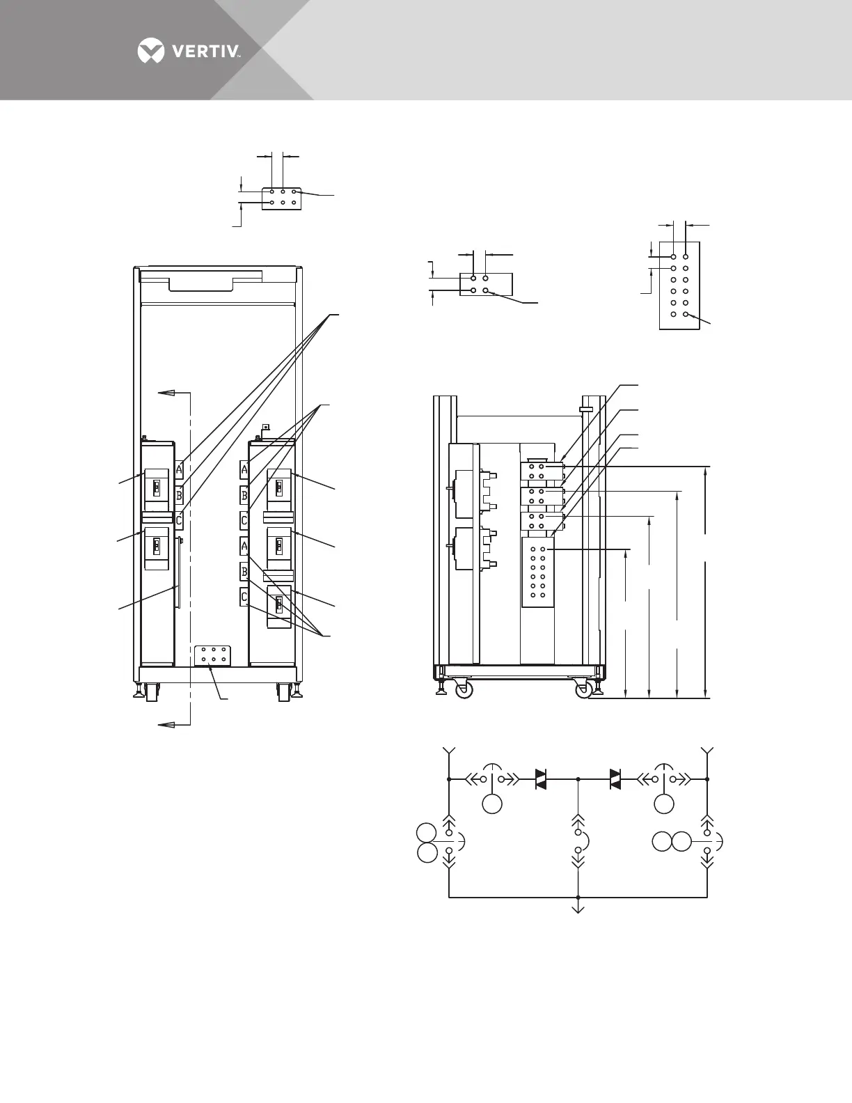
Source 1 Input
ØA, ØB, ØC
Source 2 Input
ØA, ØB, ØC
System Output
ØA, ØB, ØC
Source 1
Source 1 Input ØC
Source 1 Input ØB
Source 1 Input ØA
Source 2
System Output
ONE-LINE DIAGRAM
INPUT/OUTPUT BUS
Right Side
GROUND BUS
Front
FRONT
(Panels Removed)
CB1
CB1
CB4
A
CB4
CB3
CB2
CB2
CB5
CB3
CB5
K1
K1
K2
K2
K3
K3
PS212100
Rev. 4
NOTES
1. Top and bottom cable entry available through
removable access plates. Remove, punch to suit
conduit size and replace.
2. Control wiring and power wiring must be run in
separate conduit. Output cables should be run in
a separate conduit from input cables.
3. Aluminum and copper-clad aluminum cables
are not recommended.
4. All wiring must be in accordance with national and
local electrical codes.
5. Hardware kit is supplied for input, output, neutral
and ground cable connections. Kit includes 1/2" bolts,
washers and nuts for connecting cables to the busbars.
6. The torque requirement for 1/2" - 13 PEM nuts is
428 in./lb (48Nm).
Front
NEUTRAL BUS
Right Side
Neutral
Bus
Ground
Bus
SECTION A-A
Side View
Ø 0.51"
(13mm)
Typ.
32.2"
(818mm)
42"
(165mm)
Typical
36.7"
(932mm)
26.4"
(671mm)
41.1"
(1044mm)
A
Neutral Bus