Vertiv™ | Liebert
®
STS2
™
100-1000A, 50/60Hz User Manual | Rev. 12 | 11/2017 42
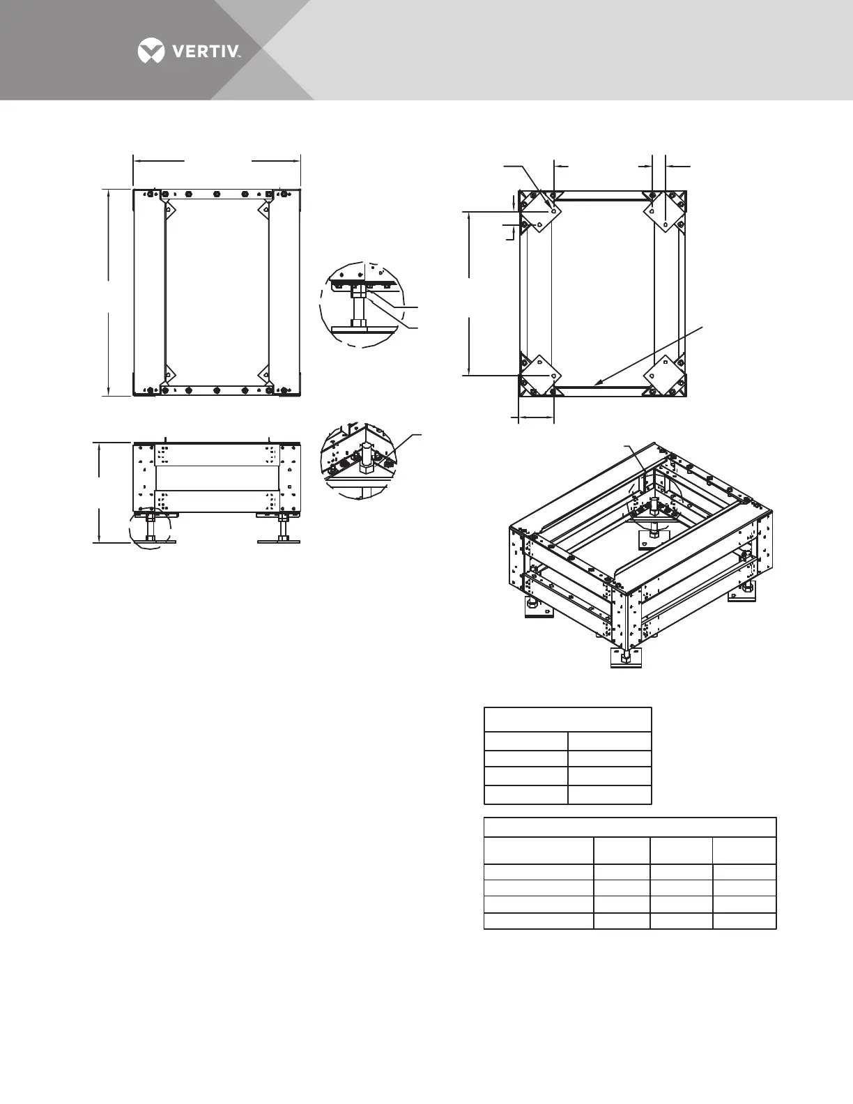
Figure 29 Installation drawing, seismic floor stand 100-250A
TOP
FRONT
BOTTOM
ISOMETRIC VIEW 250A FLOOR STAND
See
Detail A
See Detail B
HEIGHT TABLE
523401G1 18.0" 19.25" 16.00"
523402G1 24.0" 25.25" 22.00"
523403G1 30.0" 31.25" 28.00"
523404G1 36.0" 37.25" 34.00"
HARDWARE TORQUE
1.0" Nut 320 ft./lb.
M8 - 1.25
16 ft./lb.
M10 - 1.5
31 ft./lb.
M12 - 1.75
53 ft./lb.
PS215000
Rev. 3
29.9" (760mm)
29.44"
(748mm)
Typical
2.47"
(63mm)
Typical
2.47"
(63mm)
Typical
36.9"
(937mm)
17.48" (444mm)
Typical
6"
(152mm)
Typical
Nut
Nut
Jam
Nut
FOOT DETAIL A
FOOT DETAIL B
See Height
Table
Mounting
Plate
Align Foot Parallel
to Mounting Plate
as shown
INSTALLATION NOTES
1. Check all hardware for proper torque before installation.
2. Attach rear lower Liebert STS2 bracket on the floor stand using existing holes
with bent flange facing the front of the floor stand (see Figures 3 and 4 on
drawing PS215001). Use an M12-1.75x40mm cap screw, split lock washer
and torque to 53 ft./lb.
3. Loosen the Liebert STS2 adjustable leveling foot nuts (see Detail C, Drawing
PS215001). Install the rear upper Liebert STS2 bracket using existing holes
on the underside of the Liebert STS2 with tabs facing out (Figures 1 and 2,
Drawing PS215001). Install the front upper Liebert STS2 bracket using existing
holes on the underside of the Liebert STS2 with the bent flange facing to the front
(Figures 1 and 2, Drawing PS215001). Use an M12-1.75x40mm cap screw,
split lock washer and flat washer and torque to 53 ft. lb. Tighten the leveling foot nuts.
4. The floor stand can be installed next to a wall if needed; rear access is
not required. Install the floor stand with its feet oriented as shown in
the bottom view of Drawing PS215000. The floor stand must be level and all
feet must be touching the floor. Attach the floor stand feet using 1/2" x 4"
Red Head Trubolts expansion anchors (field-supplied); two per foot.
5. Roll the Liebert STS2 onto the floor stand so that the tabs on the rear upper
Liebert STS2 bracket fit into the slots on the rear lower Liebert STS2 bracket.
The tabs must extend at least 1/2" (12.9mm) through the floor stand bracket
(Figure 2, Drawing PS215002).
6. Install the lower front brackets (Figure 1, Detail A, Drawing PS215002). Attach
the bracket to the Liebert STS2 using M10-1.50x30mm cap screw, split lock washer
and flat washer. Torque to 31 ft./lb. Attach the bracket to the floor stand using
M12-1.75x40mm cap screw, split lock washer and flat washer. Torque to
53 ft./lb.
Floor Stand Part No. Height
Maximum
Height
Minimum
Height