Vertiv™ | Liebert
®
STS2
™
100-1000A, 50/60Hz User Manual | Rev. 12 | 11/2017 33
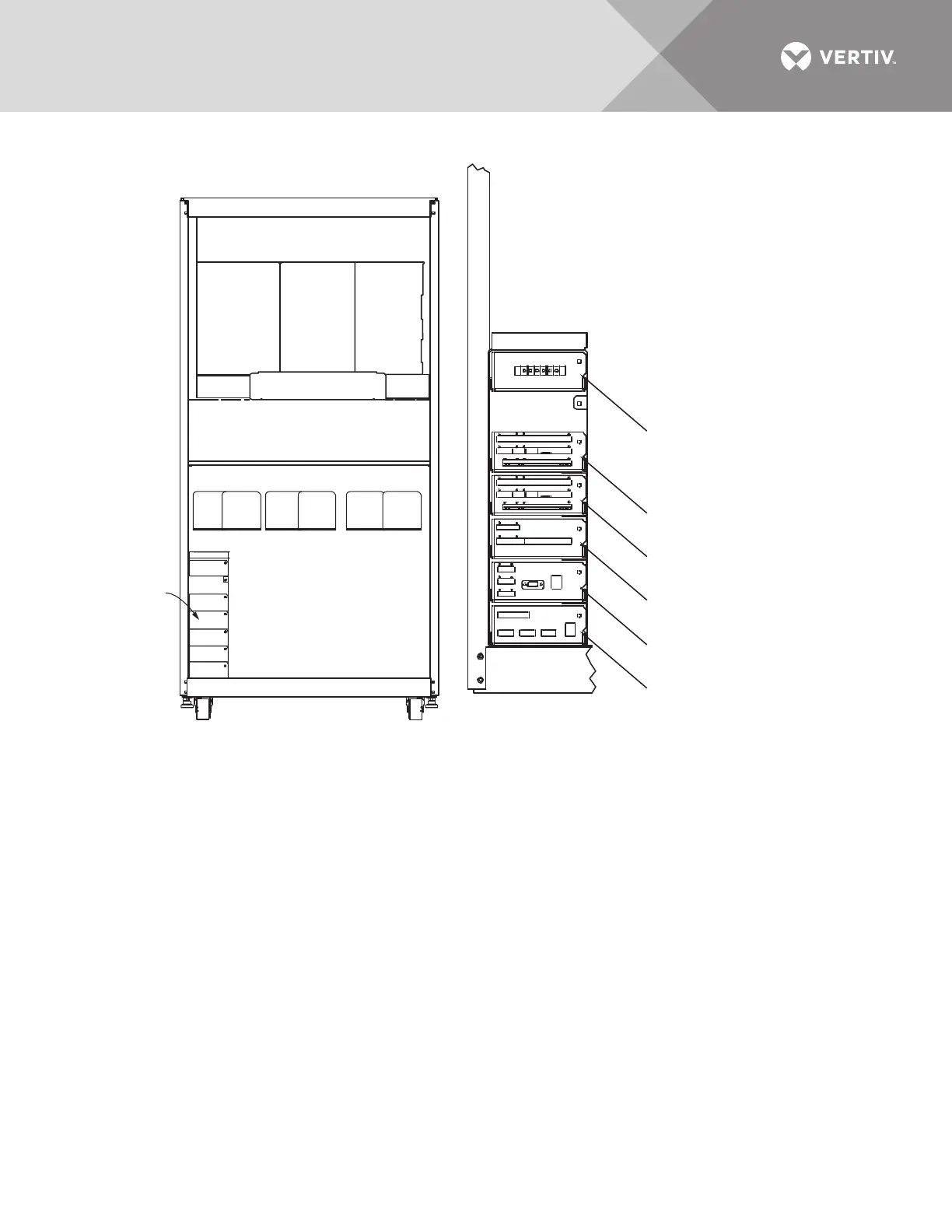
Figure 20 Control connection location diagram: 800 – 1000 amp Liebert STS2
PS213800
Rev. 2
CONTROL WIRING
Front; Door Not Shown
NOTES
1. Typical options are shown.
2. A maximum of two programmable
relay boards can be used
Remote source
Select (Option)
See Option
Location
Detail
OPTION
LOCATION DETAIL
Programmable Relay
Board (Option); See Note 2
Programmable Relay
Board (Option); See Note 2
Input Contact Isolator Board
(Option) or Programmable Relay
Board (Option); See Note 2
Comms Board for Liebert
SiteScan
Network Interface
Card (Option)