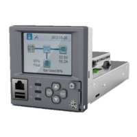
Vertiv™ NetSure™ Control Unit (NCU) User Manual
High Load Alarm: In order to identify conditions where the load requirements are exceeding the dimensioning of the Hybrid site, an
alarm will be generated. The alarm will be triggered when the maximum capacity per discharge cycle is exceeded. The threshold
value will be set as default to 40% of battery capacity. It will require capacity measurement per cycle. The alarm will be set once the
high load threshold value is reached and is reset at the beginning of the next discharge period. This alarm will help the User identify
the root cause of the under voltage condition: high demand load, the loss of capacity due to battery aging, or insufficient charge
capacity.
Capacity Discharge
The cycle period is determined by User selectable capacity discharge of the batteries and associated recharge times. The cycle
repeats continuously. It does not follow a 24hrs pattern.
Capacity Discharge and Recharge: The battery discharge period is determined by the percentage of the nominal battery capacity
[Ah] that will be discharged per cycle.
The depth of discharge [DOD] per cycle is User selectable in the range 20% to 80%. Default setting is 60%. The value is set as
battery capacity at the end of each discharge period. Therefore, if a 60% discharge is chosen, the discharge value is set to 40%.
The time to recharge to full battery capacity depends on battery capacity at the start of the charge cycle and the available recharge
current.
When the additional charge time has been reached; the generator will be stopped, the recharge cycle will end, and discharge cycle will
be initiated.
For practical purposes, the battery capacity at the end of every recharge period is set to 100% as long as Step1, Step 2, and Step 3
have elapsed.
If end of charge is not reached within the set maximum hours, the recharge will be terminated and discharge cycle will be initiated.
1.3.10 Supervisory Module (SM Modules) Monitoring
Various devices (supervisory modules) can be connected to the NCU to extend its monitoring capabilities.
1.3.11 Maximum Current Limit Function
The current available from the rectifiers can be limited (in AMPS) from 10% to 121% of combined rectifier capacity. The factory setting
is 121% unless otherwise specified. The current available from the converters can be programmed (in AMPS) from 50% to 116% of
combined converter capacity. The factory setting is 116% unless otherwise specified. Refer to the NCU Configuration Drawing (C–
drawing) supplied with your system documentation for your system’s settings.
See also “Checking the Controller’s Current Limit Point after Adding or Removing a Rectifier or Converter Module” on page 37.
1.3.12 Communications Function
The NCU is able to communicate with different equipment or, connect to different equipment for communication. See Figure 1.7.
a) 10M/100M Ethernet Port: The NCU can communicate with a supervisory computer or other devices through its 10M/100M
Ethernet port. The communication cable shall be a shielded cable. The Ethernet port is located on the front panel of the
NCU. This port supports Dynamic Host Configuration Protocol (DHCP) function.
NOTE!
Some systems may have an IB4 board with a second Ethernet port. The IB4 board is connected to the NCU’s
backplane connector (USB) via a factory provided cable. Refer to your system’s documentation for location of the IB4 board
(if furnished).
b) IB2 (Interface Board) and EIB (Extended Interface Board): Some systems may have an IB2 (Interface Board) and/or EIB
(Extended Interface Board) connected to the NCU. Each IB2 board provides eight (8) dry relay outputs. Each EIB board
provides five (5) dry relay outputs. Every relay output has a set of NC (normally close) and NO (normally open) contacts.

 Loading...