Chapter 4 Deployment of the CPU 21x-2BT10 with TCP/IP Manual VIPA CPU 21x
4-28 HB103E - Rev. 05/45
You receive the following graphical display for every PLC station and their
component. By selecting the single components, the context menu offers
you several functions:
CPU
315-2
DP MPI CP
343-1
Station 1
1
1 2
4
3
1 Station
This includes a PLC station with rack, CPU and communication
components. Via the context menu you may configure a station
added from the net objects and its concerning components in the
hardware configurator. After returning to NetPro, the new configured
components are shown.
2 CPU
A click onto the CPU shows the connection table. The connection
table shows all connections that are configured for the CPU.
3 Internal communication components
This displays the communication components that are available in
your CPU. For the 21xNET-CPUs are configured as CPU 315-2DP
the internal components do not show the CP.
Due to this, the CP that is included in the 21xNET-CPU must be
configured as external CP at slot 4. The CP is then also shown in
NetPro as external CP in the station.
4 CP
The CP must always be configured as Siemens CP 343-1 in the
hardware configuration.
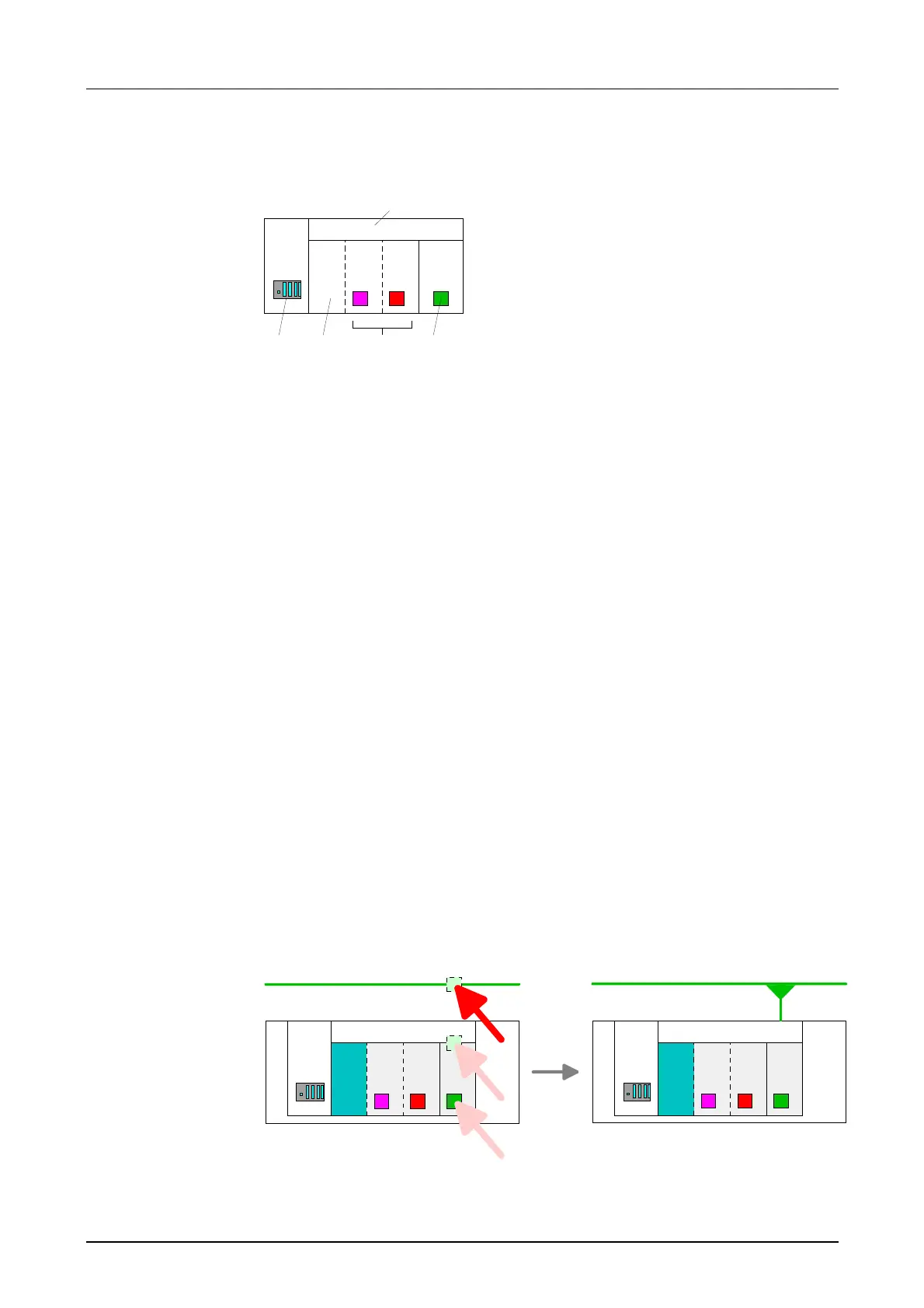
NetPro offers you the option to link-up the communicating stations. You
may link-up the stations via the properties in the hardware configuration or
graphically via NetPro. For this you point the mouse on the colored net
mark of the according CP and drag and drop it to the net you want to link.
Now the CP is linked up to the wanted net by means of a line.
CPU
315-2
DP MPI CP
343-1
Station 1
Industrial Ethernet
CPU
315-2
DP MPI CP
343-1
Station 1
Industrial Ethernet
PLC stations
Link up stations

 Loading...


