Manual VIPA CPU 21x Chapter 5 Deployment CPU 21x-2BT02 with H1 / TCP/IP
HB103E - Rev. 05/45 5-25
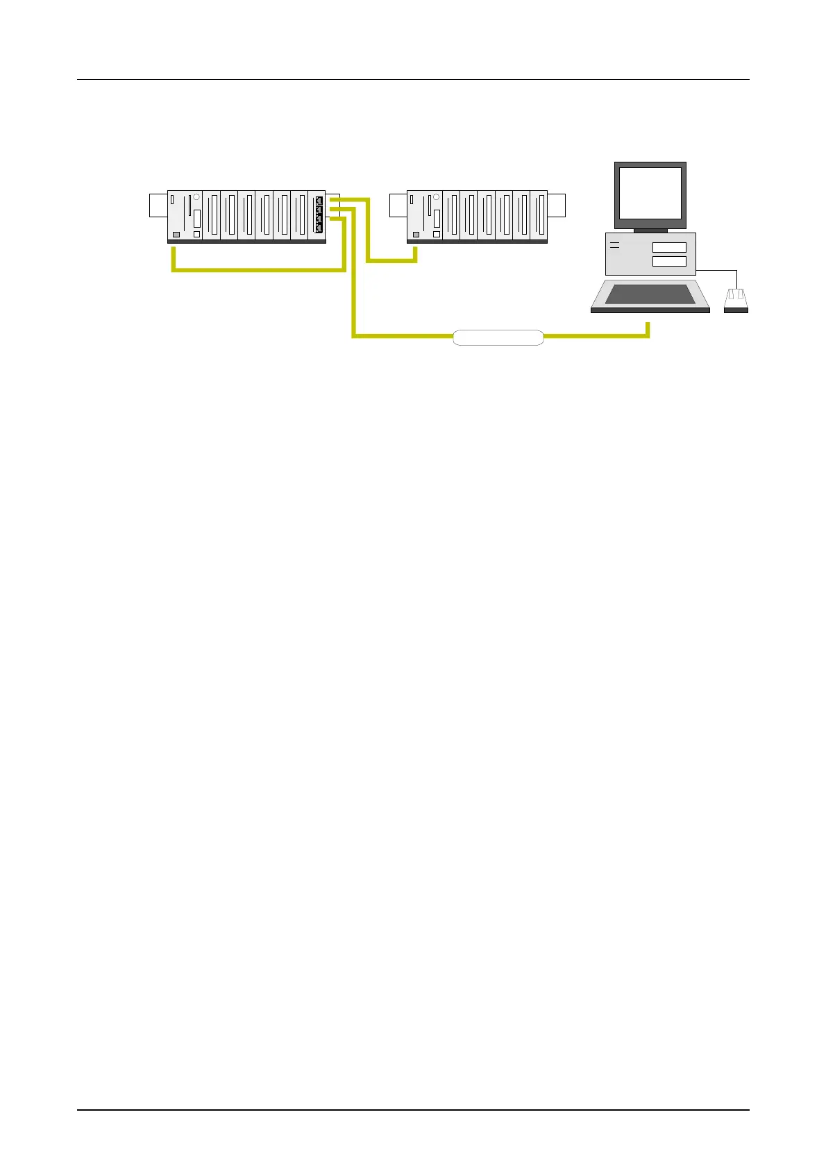
Station 1
System 200V
CPU 21xNET
Station 2
System 200V
CPU 21xNET
WinNCS
Ethernet
The introductory example is the application of a communication task,
described below. Both of the CPUs run with the same PLC program, only
the configuration of the CPs have to be adjusted.
Both stations are sending and receiving 16 data words per second.
• Data block DB11 transfers the data words DW0 to DW15 at an interval
of 1s. Data word DW0 in DB11 is used as message counter. It is only
incremented, if the preceding send command was processed correctly
(completed without error). The remaining data words (DW1 to DW15)
may be used for the transfer of user data.
• The receiving station stores the data in DB12 (DW 0 to DW 15).
• SEND is configured with job number A-No. = 1 and with a page frame
offset SSNR = 0.
• RECEIVE is configured with job number A-No. = 11 and a page frame
offset SSNR = 0.
• The source and destination parameters have to be configured directly.
At this point the purpose and the required settings have been outlined. The
programs provide additional details of the configuration of the handler
blocks. A detailed description of a suitable configuration of the CPs under
control of H1 or TCP/IP is also included.
Structure
Purpose of the
PLCs

 Loading...


