Manual VIPA CPU 21x Chapter 2 Hardware description
HB103E - Rev. 05/45 2-15
In addition to the components described in the section on the CPU 21x the
CPU 21x-2BT10 module is provided with further LEDs and an Ethernet
interface located at the left-hand side of the module.
The LEDs are located on the left-hand side of the front panel and indicate
communication activities.
The table below shows the color and the meaning of these LEDs.
Name Color Description
RN green CP RUN
On: CP project is loaded
Off: CP is reset (no project)
ST yellow CP STOP
On: CP status is reset
Off: CP Project is transferred
IF red On: Internal CP error
L/A green Link/Activity:
On: physically connected to Ethernet
Off: no physical connection to Ethernet
Blinks: Ethernet activity
S green Transfer speed:
On: 100MBit
Off: 10MBit
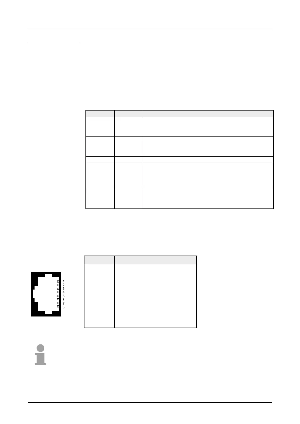
An RJ45 jack provides the interface to the twisted pair cable, required for
Ethernet. The pin assignment of this jack is as follows:
8pin RJ45 jack:
Pin Assignment
1 Transmit +
2 Transmit -
3 Receive +
4 -
5 -
6 Receive -
7 -
8 -
Note!
For more detailed information on twisted pair networks refer to chapter
"Deployment of the CPU 21x-2BT10".
CPU 21x-2BT10
LEDs
Ethernet interface

 Loading...


