Chapter 2 Hardware description Manual VIPA CPU 21x
2-16 HB103E - Rev. 05/45
In addition to the components described in the section on the CPU 21x the
CPU 21x-2BT02 module is provided with further LEDs and an Ethernet
interface located at the left-hand side of the module.
The LEDs are located on the left-hand side of the front panel and indicate
communication activities.
The table below shows the color and the meaning of these LEDs.
Name Color Description
PW green Indicates CPU power on
TxD green Transmit data
RxD green Receive data
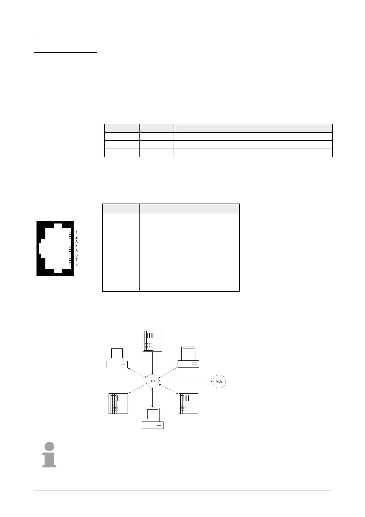
An RJ45 jack provides the interface to the twisted pair cable, required for
Ethernet. The pin assignment of this jack is as follows:
8pin RJ45 jack:
Pin Assignment
1 Transmit +
2 Transmit -
3 Receive +
4 -
5 -
6 Receive -
7 -
8 -
Star topology
A twisted pair network can only have a star topology. For this purpose a
hub is required as the central node:
Note!
For more detailed information on twisted pair networks refer to chapter
"Deployment of the CPU 21x-2BT02".
CPU 21x-2BT02
LEDs
Ethernet interface

 Loading...


