Manual VIPA CPU 21x Chapter 2 Hardware description
HB103E - Rev. 05/45 2-17
In addition to the components described in the section on the CPU 21x the
CPU 21xDPM module is provided with 4 more LEDs and a Profibus
interface.
The LEDs are located in the left half of the front panel and they are used
for diagnostic purposes. The following table shows the color and the
significance of these LEDs.
Name Color Description
RN green DP-Master-RUN
On: Master status is RUN. The slaves are being
accessed and the outputs are 0 ("clear" state).
On with DE: Master status is "operate". and is
communicating with the slaves.
IF red Initialization error
On: Error in Profibus configuration
DE yellow DE (Data exchange)
On: Indicates Profibus communication activity.
ER red Error
On: Slave has failed
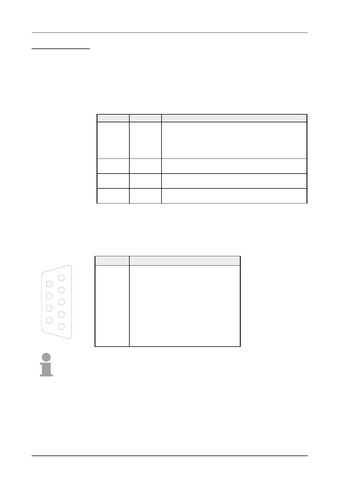
The CPU 21xDPM is connected to the Profibus system by means of a 9pin
jack. The pin assignment of this interface is as shown:
9pin Profibus D-type jack:
Pin Assignment
1 Shield
2 n.c.
3 RxD/TxD-P (Line B)
4 RTS
5 M5V
6 P5V
7 n.c.
8 RxD/TxD-N (Line A)
9 n.c.
Note!
Refer to the chapter "Deployment of the CPU 21xDPM" for details on the
Profibus master.
CPU 21xDPM
LEDs
Profibus interface
5
4
3
2
1
9
8
7
6

 Loading...


