Chapter 2 Hardware description Manual VIPA CPU 21x
2-18 HB103E - Rev. 05/45
In addition to the components described in the section on the CPU 21x the
CPU 21xDP module is provided with 3 more LEDs and a Profibus interface.
The LEDs are located in the left half of the front panel and they are used
for diagnostic purposes. The following table shows the color and the
significance of these LEDs.
Name Color Description
ER red Error
On: Error in Profibus part detected respectively
CPU has been stopped.
Flashing (2Hz): Initialization error
Flashing (10Hz): Supply voltage < DC18V
Flashing alternately with RD: Configuration error
(error at Master configuration)
Flashing simultaneously with RD: Error in
parameterization
RD green Ready
On: Data transfer via back plane bus
Flashing: Self-test result is positive (READY) and
successful initialization
DE green DE (Data exchange)
On: Indicates an active Profibus communication.
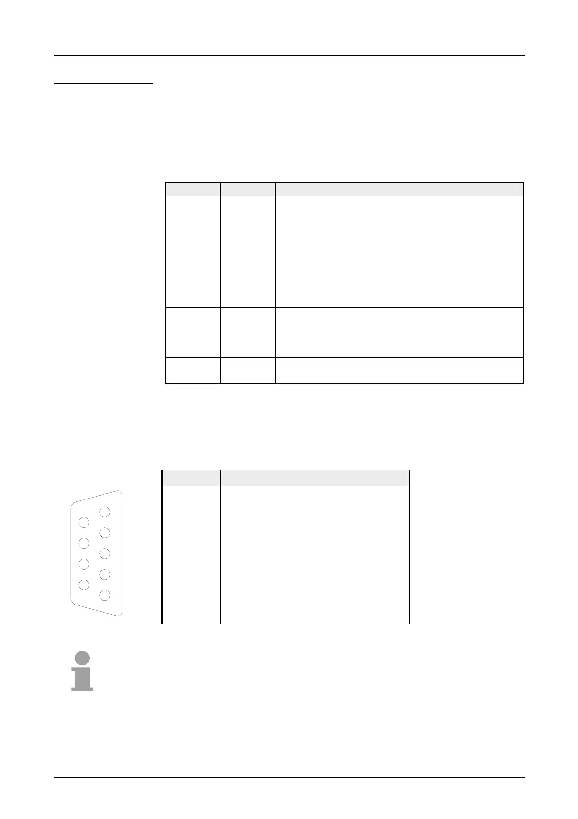
The CPU 21xDP is connected to the Profibus system by means of a 9pin
jack. The pin assignment of this interface is as shown:
9pin Profibus D-type jack:
Pin Assignment
1 Shield
2 n.c.
3 RxD/TxD-P (Line B)
4 RTS
5 M5V
6 P5V
7 n.c.
8 RxD/TxD-N (Line A)
9 n.c.
Note!
Refer to the chapter "Deployment of the CPU 21xDP" for details on the
Profibus.
CPU 21xDP
LEDs
Profibus interface
5
4
3
2
1
9
8
7
6

 Loading...


