Manual VIPA CPU 21x Chapter 2 Hardware description
HB103E - Rev. 05/45 2-19
In addition to the components described in the section on the CPU 21x the
CPU 21xCAN module is provided with 4 more LEDs and a CAN interface.
The LEDs are located in the left half of the front panel and they are used
for diagnostic purposes. The following table shows the color and the
significance of these LEDs.
Name Color Description
RN green CAN master RUN
ON: CAN master state is RUN
OFF: CAN master state is STOP
ER red Error
ON: During initialization and at slave failure
OFF: All slaves are in the state "operational"
BA yellow BA (Bus active)
On: CAN bus communication respectively state
"operational"
Blinking (1Hz): State "pre-operational".
IF red Initialization
ON: Initialization error at wrong parameterization.
Off: Initialization is OK.
Note!
If all LEDs are blinking with 1Hz, the CAN master awaits valid parameters
from the CPU. If the CAN master is not supplied with parameters by the
CPU his LEDs get off after 5s.
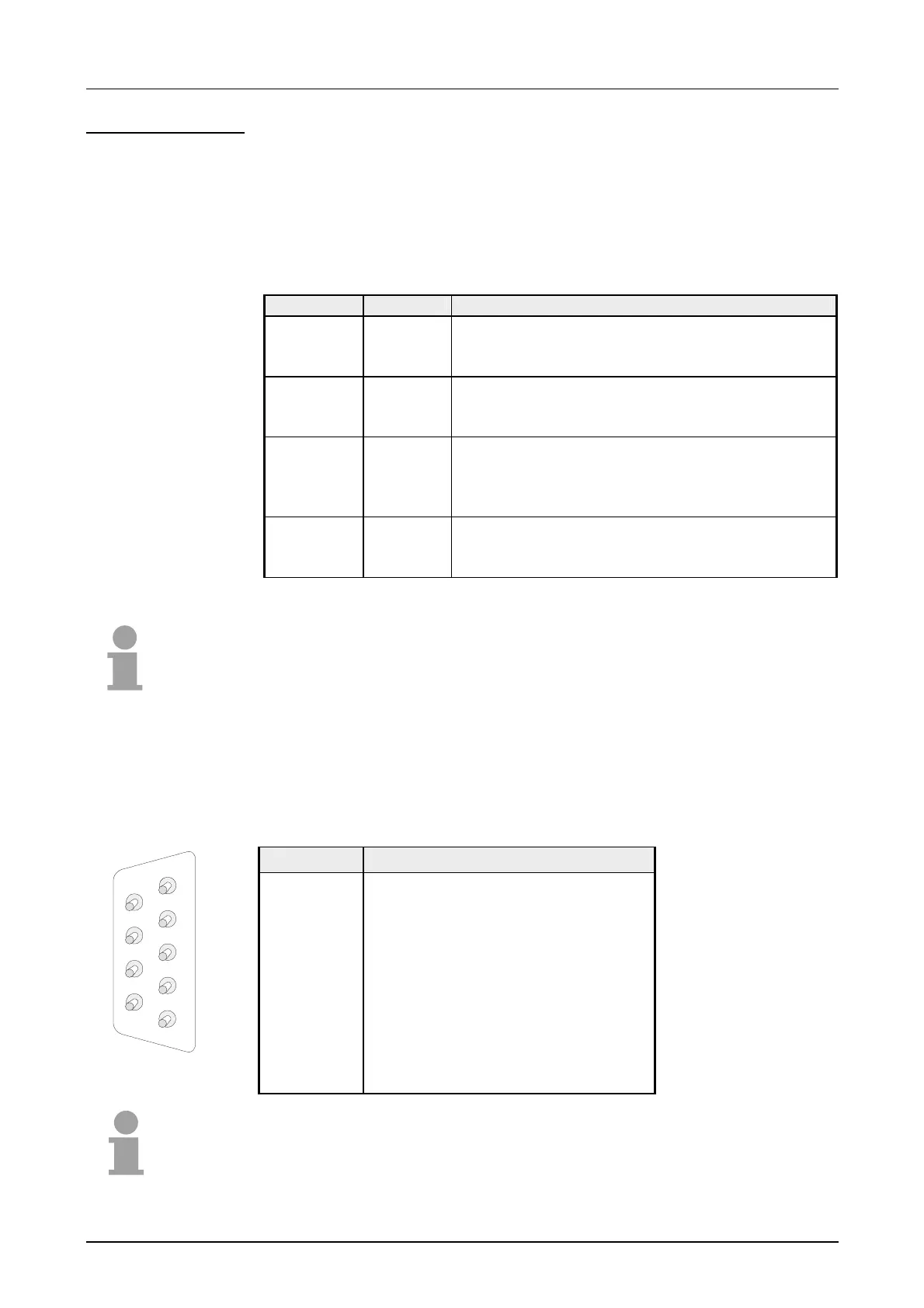
The CPU 21xCAN is connected to the CAN system by means of a 9pin
plug. The pin assignment of this interface is as shown:
9pin CAN D-type plug:
Pin Assignment
1 reserved
2 CAN low
3 CAN Ground
4 reserved
5 Screen
6 Ground 24V
7 CAN high
8 reserved
9 +DC 24V
Note!
More details on the CAN master see chapter "Deployment CPU 21xCAN"!
CPU 21xCAN
LEDs
CAN interface
1
2
3
4
5
6
7
8
9

 Loading...


