Chapter 2 Hardware description Manual VIPA CPU 21x
2-20 HB103E - Rev. 05/45
Additional to the components described before, the CPU 21x with order no.
21x-2BS12 has an RS232C interface and the CPU 21x with order no.
21x-2BS32 an RS485 interface.
The LEDs are located in the left half of the front panel and they are used
for diagnostic purposes. The following table shows the color and the
significance of these LEDs.
Name Color Description
Rx green Interface receive data
Tx green Interface transmit data
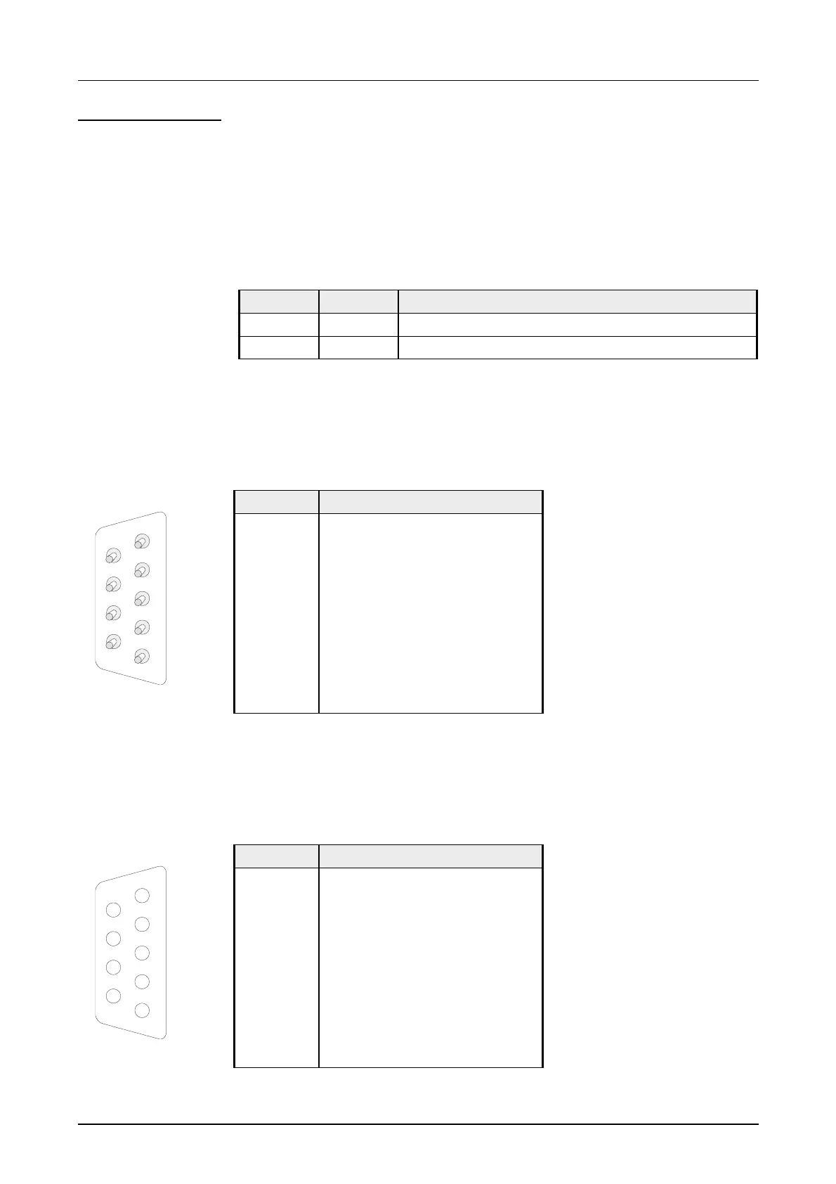
Via 9pin jack, you may establish a serial RS232C point-to-point connection.
The pin assignment of this interface is as shown:
9pin plug
(CPU 21x-2BS12)
Pin Assignment
1 CD-
2 RxD
3 TxD
4 DTR-
5 GND
6 DSR-
7 RTS-
8 CTS-
9 RI-
Via 9pin slot, you may establish a serial RS485 bus connection. The pin
assignment of this interface is as shown:
9pin jack
(CPU 21x-2BS32)
Pin Assignment
1 n.c.
2 n.c.
3 RxD/TxD-P (Line B)
4 RTS
5 M5V
6 P5V
7 n.c.
8 RxD/TxD-N (Line A)
9 n.c.
CPU 11xSER-1
LEDs
RS232C interface
RS485 interface
1
2
3
4
5
6
7
8
9
5
4
3
2
1
9
8
7
6

 Loading...


