Tech. Dok. / L23 880 02 / 01.00.02 © MICHAEL WEINIG AG
Basic setting
4-2 Profimat 23 E
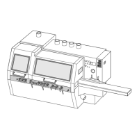
Setting spindles
The tool must be set in relation to the following
fence or table in order to avoid snipes. The fol-
lowing example refers to the right-hand spindle:
• Hold setting straight edge against fence and
adjust tool towards setting straight edge until at
least one cutting edge touches the bar. Turn the
tool by hand in the direction opposite to that of
cutting during the adjustment.
• The tool is correctly set when the rubbing
movement of the cutting edge against the setting
straight edge can be faintly felt but not heard.
• Set the mechanical counter in this position.
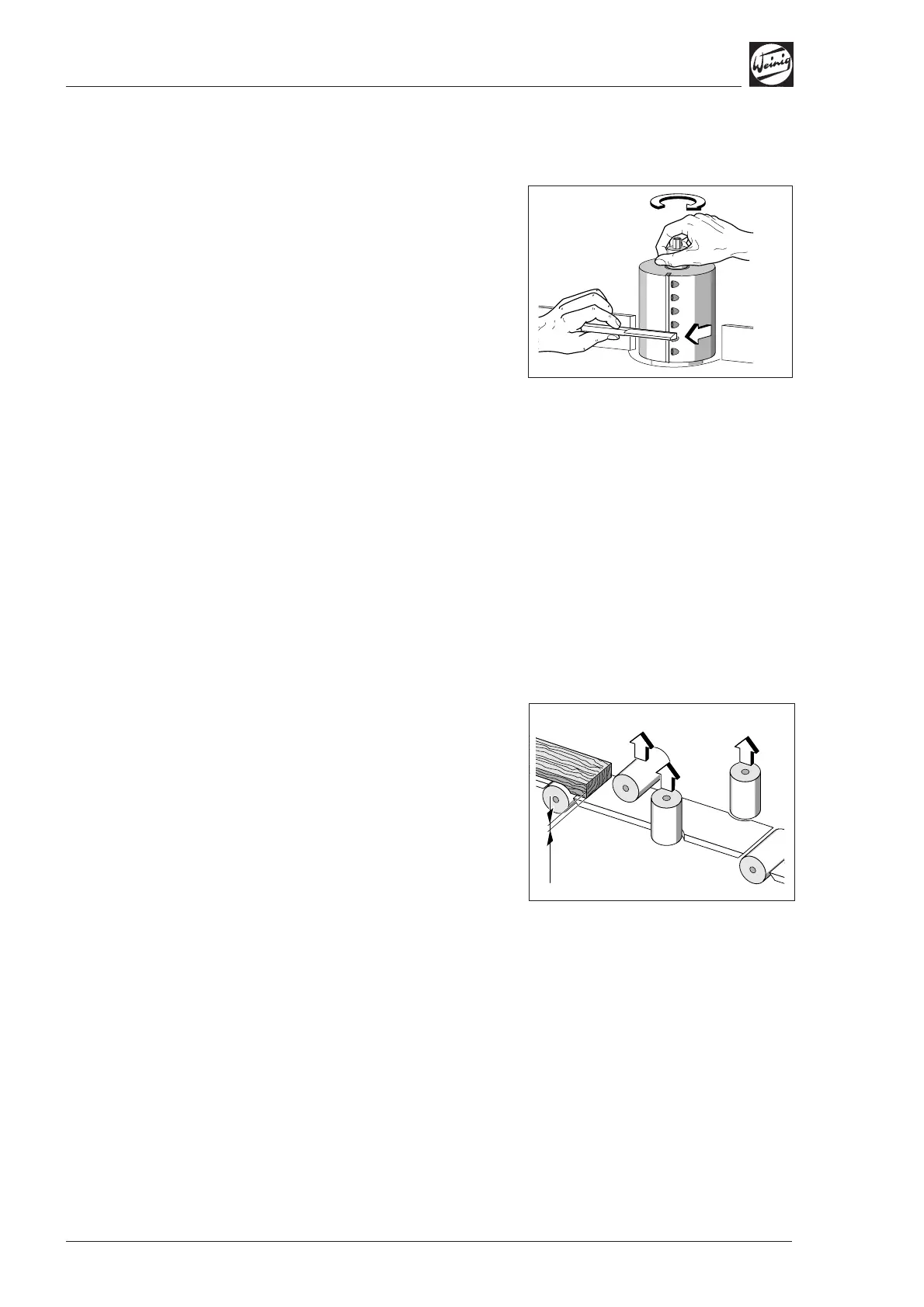
Pressure elements
When the tools have been set to their basic
position, the pressure elements and table plates
must be set as close as possible to the largest tool
cutting circle.
Note the following point for the
bottom spindle:
If a chip is removed on the last bottom spindle, this
must be taken into account on the top spindle when
setting the numerical indicators, e.g. 0.5 mm
(0.020").
Height correction
The chip removal in axial direction must be taken
into account, e.g. 0.5 mm (0.020"), when
profiling with the vertical spindles.
0,5
0,5
0,5
0,5