Installation and Connection
Installation Diagram 8-Pushbutton Version
Even when the auxiliary voltage is switched-off, unsafe voltages might remain
at the device connections.
The installation diagram shown in this section is exclusively valid for devices
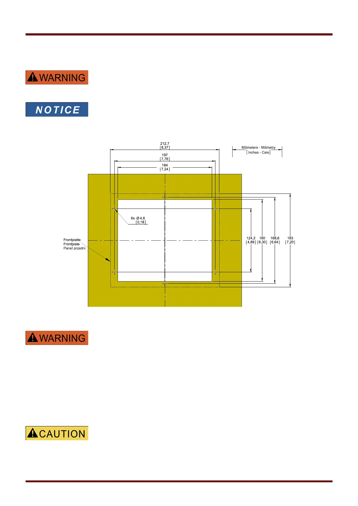
with 8 pushbuttons at the front side of the HMI.
(INFO-, C-, OK-, CTRL-Pushbutton and 4 Softkeys (Pushbuttons)).
B2 Housing Door Cut-out (8-Pushbutton Version). (All dimensions in mm, except dimensions in brackets [inch].)
The housing must be carefully grounded. Connect a ground cable
(protective earth, 4 to 6 mm
2
[AWG 11‒9], tightening torque 1.7 Nm
[15 lb⋅in]) to the housing, using the screw that is marked with the ground
symbol (at the rear side of the device).
Moreover, the power supply card needs a separate ground connection
(functional earth, min. 2.5 mm
2
[≤ AWG 13], tightening torque 0,56 ‒
0,79 Nm [5‒7 lb⋅in ]). See the “Terminal Marking” diagram in Section “DI-4
X – Power Supply and Digital Inputs” to check for the correct terminal.
All grounding connections (i. e. protective and functional earth) must be
low-inductance, i. e. as short as possible, and national standards – if
applicable – must be followed.
Be careful. Do not overtighten the mountings nuts of the relay
(M4 metric 4 mm). Check the torque by means of a torque wrench (1.7 Nm
[15 In⋅lb]). Over-tightening the mounting nuts could cause personal injury or
damage the relay.
32 MCDGV4 DOK-HB-MCDGV4-2E