Input, Output and LED Settings
Input, Output and LED Settings
Configuration of the Digital Inputs
Set the following parameters for each of the digital inputs:
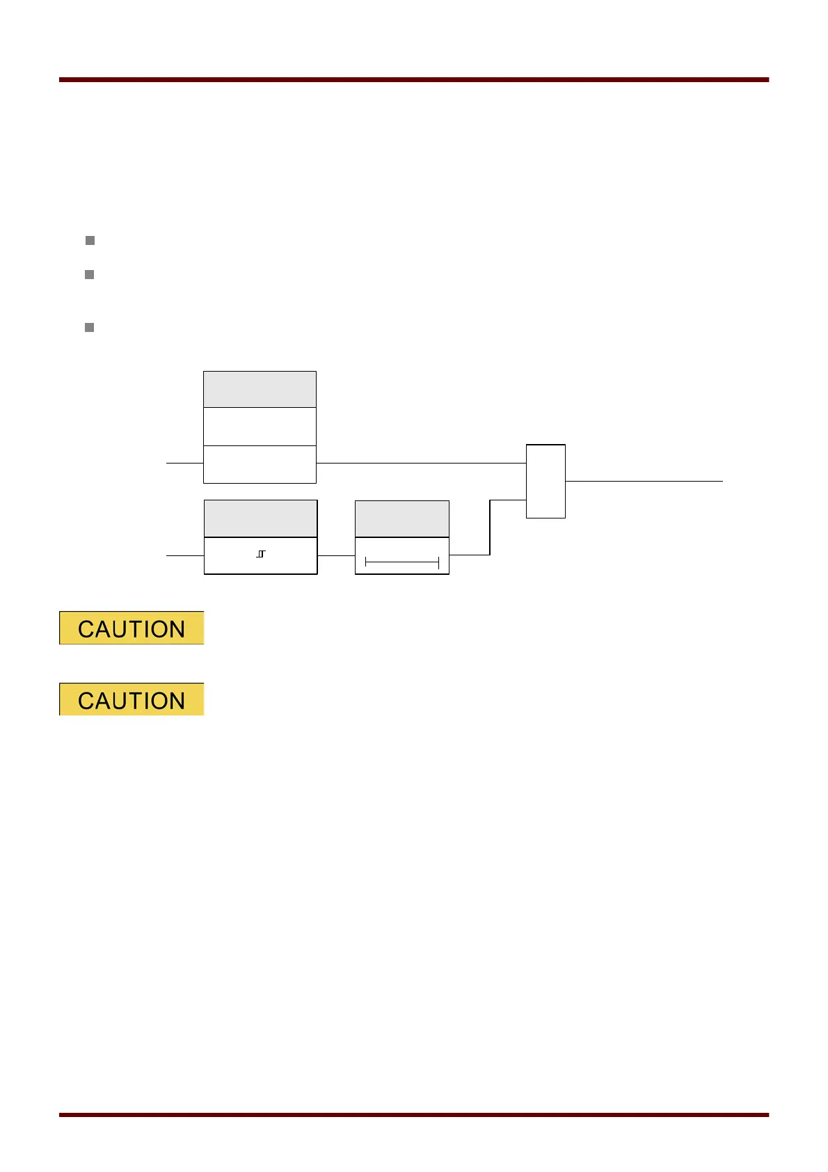
»Nominal voltage«
»Debouncing time«
: A state change will only be adopted by the digital input after the debouncing time has
expired.
»Inverting«
(where necessary)
The debouncing time will be started each time the state of the input signal
alternates.
In addition to the debouncing time that can be set via software, there is always
a hardware debouncing time (approx 12 ms) that cannot be turned of.
108 MCDGV4 DOK-HB-MCDGV4-2E