Input, Output and LED Settings
Assignment of Digital Inputs
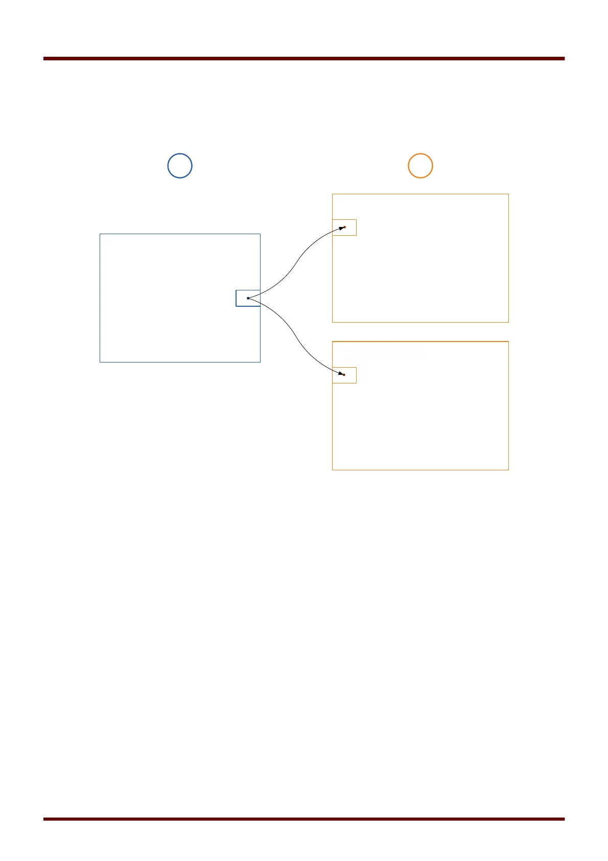
There are two options available in order to determine where a Digital Input should be assigned to.
Option 1 – Assigning a Digital Input onto one or mutliple modules.
Adding an assignment:
Within menu [Device Parameter\Digital Inputs] Digital Inputs can be assigned onto one or multiple targets.
Call up the Digital Input (Arrow right on the DI). Click on the Softkey
»Parameter Setting/Wrench«
. Click on
»Add«
and assign a target. Assign where required additional targets.
Deleting an assignment:
Select as described above a Digital Input that should be edited at the HMI.
Call up the assignments of the Digital Input (Arrow-right on the DI) and select the assignment that should be
removed/deleted (Please note, this has to marked with the cursor). The assignment can now be deleted at
the HMI by means of the Softkey »
Parameter setting«
and selection of »
remove«
. Confirm the parameter
setting update.
Option 2 – Connecting a Module Input with a Digital Input
Call a module. Within this module assign a Digital Input onto a module input. Example: A protection module
should be blocked depending on the state of a Digital Input.. For this assign onto the blocking input within the
Global Parameters the Digital Input (e.g. Ex Blo 1).
109 MCDGV4 DOK-HB-MCDGV4-2E