Protective Elements
Application Options Required Settings
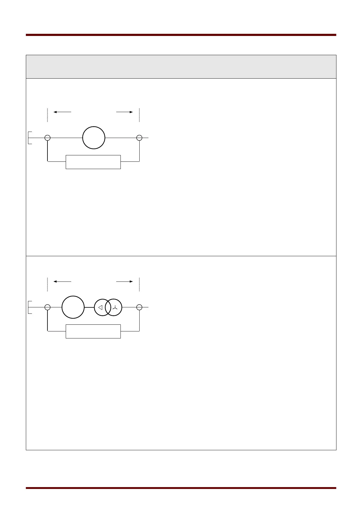
ANSI 87GP
– Generator Differential
Protection (Bus connection)
To be used if only the generator is to be
protected by the differential protection.
Note1
: „CT Neutral” at generator neutral must be connected to the
device current input X3 (W1) and “CT Mains” at generator terminal
must be connected to device current terminal X4 (W2).
Set the Mode within the Device Planning.
Where? Within [Device Planning]
Set „Transformer.Mode=not used“
Set the Field Parameters of the Generator.
Where? Within [Field Para\Generator]
Set the Differential Protection Parameters.
Where? Within [Protection Para\Set [x]\Diff-Prot]
Note2
: Settings for harmonic and CT saturation detection like Stab
H2/H4/H5 can be set to inactive if they are probably not used for
Generator Phase Differential Protection.
ANSI 87UP
– Unit Differential Protection
To be used if the generator and the step-up
transformer are to be protected by one
phase differential protection element.
Note1
: “CT Neutral” at generator neutral must be connected to the
device current input X3 (W1) and “CT Mains” at transformer bus
side must be connected to device current terminal X4 (W2).
Set the Mode within the Device Planning.
Where? Within [Device Planning]
Set „Transformer.Mode=use“
Set the Field Parameters of the Generator
1)
.
Where? Within [Field Para\Generator]
Set the Field Parameters of the Transformer
1)
(step up).
Where? Within [Field Para\Transformer]
Set the Differential Protection Parameters.
Where? Within [Protection Para\Set [x]\Diff-Prot]
Note2
: Settings for harmonic and CT saturation detection like Stab
H2/H4/H5 can be set to active if they are probably used for Unit
Phase Differential Protection.
1)
For Unit Differential Protection the Transformer Rated Voltage on the generator side (Pri V W1) should be the
same as the generator Generator Rated Voltage (Ph-Ph).
627 MCDGV4 DOK-HB-MCDGV4-2E