Protective Elements
Setting Parameter Description
»Mho Pos.Imp.Reach«
MHO characteristic: Positive Impedance Reach
»Mho Pos.Imp.Angle«
MHO characteristic: Positive Impedance Angle
»Mho Offs.Imp.Reach«
MHO characteristic: Offset Impedance Reach
»Mho Offs.Imp.Angle«
MHO characteristic: Offset Impedance Angle
»Direction angle 1«
»
Direction angle 2
«
Angles that confine the impedance area. (Note that the angles are always measured
counter-clockwise from the positive R-axis.)
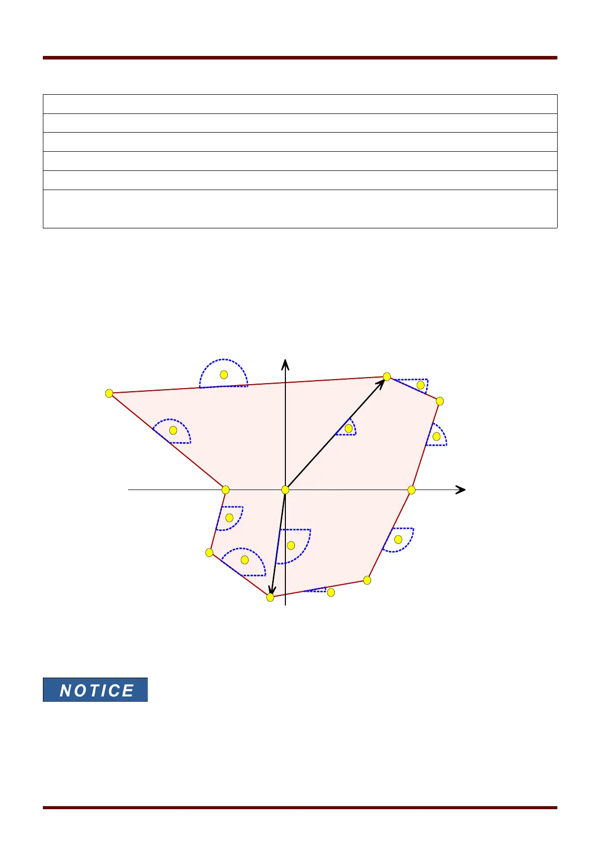
• Polygon:
Modern powerful digital protection relays allow for very sophisticated polygon characteristics, which often
offers a better coverage of different fault and operating conditions. The downside of the great flexibility in
shaping the operating area is that a lot of different setting parameters are involved.
Operating area (colored in bright red) of type polygon, with »Direction enable« = “inactive”.
(The table below lists which distances are referred to by the circled numbers, and which angles are referred to by
the circled letters.)
Note that all angles in this construction are always measured counter-clockwise
from the R-axis.
819 MCDGV4 DOK-HB-MCDGV4-2E


 To Next Page