Protective Elements
Interaction with Distance Protection
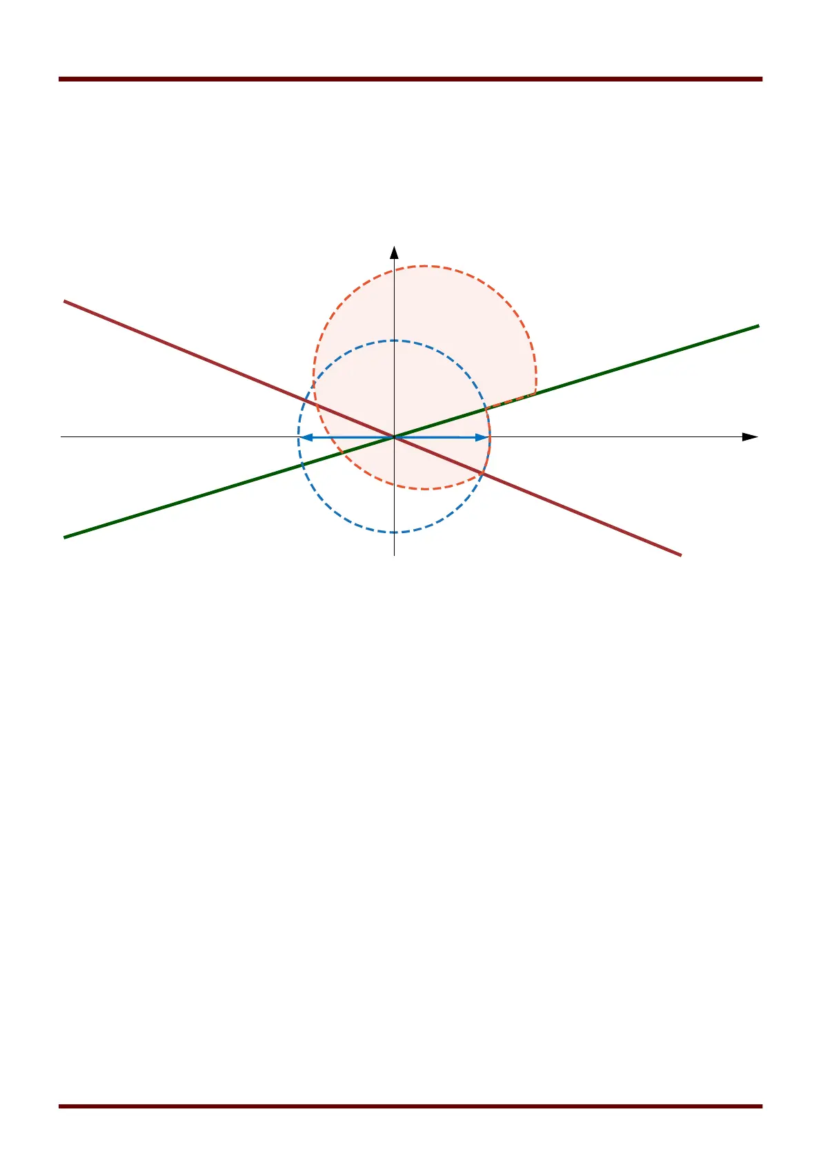
To inhibit the operation of the distance protection element for these high load areas, the »Operate« signal has to be
assigned to the input »Z . Blo by LB« of the respective distance protection element. Thereby, the load blinder area
is removed from the tripping zone of the appropriate distance protection function. The resulting tripping zone is
shown in bright-red color in the following diagram.
Distance Protection tripping zone (red area) with active Load Blinder.
The load blinder function should work only under overload conditions which are characterized by (almost) only the
positive phase sequence component in current measurements. Vice versa, it must be disabled in case of
unsymmetrical faults, which are characterized by significant negative phase sequence component. Therefore there
are two more settings, a maximum value
»I2 max«
for the negative sequence current, and a minimum value
»I1
min«
for the positive sequence current: The Load Blinder function is active only if the positive sequence current
I1
is
above
»I1 min«
and if the negative sequence current
I2
is below
»I2 max«
. The default values of
»I1 min«
,
»I2
max«
should already fit to typical applications; nevertheless it is recommended to check these settings during
commissioning and adapt them to the local fault and load conditions if necessary.
845 MCDGV4 DOK-HB-MCDGV4-2E