Home
Woodward
Other
HighPROTEC
Page 92
Woodward HighPROTEC - Page 92
1369 pages
Manual
Save Page as PDF
To Next Page
To Next Page
To Previous Page
To Previous Page
Loading...
Installat
ion and
Connecti
on
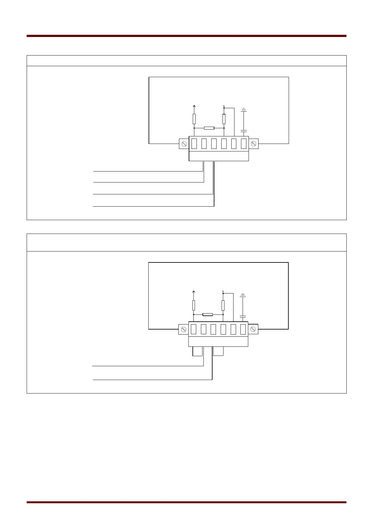
Wiring exampl
e, Device
in the middle
of the
bus
Wiring exampl
e, Device
at the end
of the
bus
(setting wire
jum
pers to activate th
e integr
ated T
erminal R
e
sistor)
92
MCDGV4
DOK-HB-MCDGV4-2E
6
4
5
3
2
1
+
5V
G
ND
R1
=
5
60
R
2 =
12
0
P
r
o
tect
i
ve
R
el
a
y
P
P
*
N
N
*
R
1
R2
R
1
HF
S
hi
el
d
6
4
5
3
2
1
+
5V
G
ND
R
1
=
56
0
R2
=
1
20
P
r
o
tect
i
ve
R
el
a
y
P
N
R
1
R2
R1
HF
S
hi
el
d
91
93
Table of Contents
Main Page
MCDGV4 Functional Overview
2
Order Code
3
Table of Contents
5
Table of Contents
6
Comments on the Manual
11
Information Concerning Liability and Warranty
11
Important Definitions
12
Important Information
14
Scope of Delivery
16
Storage
17
Waste Disposal
17
Symbols
18
General Conventions
20
Load Reference Arrow System
25
Device
26
Device Planning
26
Device Configuration Parameters of the Device
27
Three-Side-View - 19
29
Installation and Connection
29
Three-Side-View - 8-Pushbutton Version
31
Installation Diagram 8-Pushbutton Version
32
Assembly Groups
33
Grounding
34
Legend for Wiring Diagrams
35
Slot X1: Power Supply Card with Digital Inputs
37
Slot X2: Relay Output Card
41
Slot X3: CT Ntrl - Current Transformer Measuring Inputs
44
Slot X4: CT Mains - Current Transformer Measuring Inputs
45
Slot X5: Multi Input - Output Card
59
Slot X6: Voltage Measuring Card with Digital In- or Outputs
66
DI8 X- Digital Inputs
69
Slot X100: Ethernet Interface
88
Slot X103: Data Communication
90
Slot X104: IRIG-B00X and Supervision Contact
99
Navigation - Operation
102
Basic Menu Control
107
Input, Output and LED Settings
108
Configuration of the Digital Inputs
108
Output Relays Settings
119
Configuration of the Analog Outputs
182
Analog Inputs
190
LED Configuration
217
Security
220
Access Authorizations (Access Areas)
221
Network Access
226
Reset to Factory Defaults, Reset All Passwords
227
Smart View
229
Data Visualizer
230
Wide Frequency Range
231
Measuring Values
232
Read out Measured Values
232
Power - Measured Values
246
Energy Counter
248
Global Parameters of the Energy Counter Module
248
Direct Commands of the Energy Counter Module
248
Signals of the Energy Counter Module (States of the Outputs)
248
Statistics
253
Configuration of the Minimum and Maximum Values
253
Configuration of the Average Value Calculation
254
Direct Commands
256
Global Protection Parameters of the Statistics Module
256
States of the Inputs of the Statistics Module
260
Signals of the Statistics Module
261
Counters of the Module Statistics
261
System Alarms
274
Demand Management
274
Peak Values
277
Min. and Max. Values
277
THD Protection
278
Device Planning Parameters of the Demand Management
278
Signals of the Demand Management (States of the Outputs)
278
Global Protection Parameter of the Demand Management
279
States of the Inputs of the Demand Management
283
Acknowledgments
284
Manual Acknowledgment
286
External Acknowledgments
287
Manual Resets
288
Status Display
289
Operating Panel (HMI)
290
Special Parameters of the Panel
290
Direct Commands of the Panel
290
Global Protection Parameters of the Panel
290
Recorders
292
Disturbance Recorder
292
Fault Recorder
301
Event Recorder
308
Trend Recorder
310
Communication Protocols
317
SCADA Interface
317
TCP/IP Parameter
317
Modbus
319
Profibus
343
Iec60870-5-103
356
Direct Commands of the IEC60870-5-103
359
IEC60870-5-103 Input States
360
Iec61850
362
Dnp3
378
Time Synchronization
422
Sntp
429
Irig-B00X
436
Parameter Definitions
441
Parameters
441
Parameter Setting at the HMI
461
Setting Groups
465
Setting Lock
475
Device Parameters
476
Date and Time
476
Version
476
Display of ANSI-Codes
476
TCP/IP Settings
477
Direct Commands of the System Module
478
Global Protection Parameters of the System
478
System Module Input States
481
System Module Signals
482
Special Values of the System Module
484
Field Parameters
485
General Field Parameters
485
Field Parameters - Phase Differential Current
486
Field Parameters - Earth Differential Current
487
Field Parameters - Current Related
488
Field Parameters - Voltage Related
490
Field Parameters of the Generator
493
Field Parameters of the Transformer
495
Blockings
497
Permanent Blocking
497
Temporary Blocking
497
To Activate or Deactivate the Tripping Command of a Protection Module
499
Activate, Deactivate Respectively Block Temporarily Protection Functions
501
Module: Protection (Prot)
507
General Alarms and General Trips
509
Direction Determination
514
Direct Commands of the Protection Module
515
Global Protection Parameters of the Protection Module
515
Protection Module Input States
516
Protection Module Signals (Output States)
516
Protection Module Values
517
Directional Features of the Overcurrent Stages I[N]
519
Directional Features for Measured Ground Fault Elements 50N/51N
520
Directional Features for Calculated (IG Calc) Ground Fault 50N/51N
522
Switchgear/Breaker - Manager
525
Single Line Diagram
526
Notes on Special Switchgears
528
Switchgear Configuration
530
Switchgear Wear
541
Control - Example: Switching of a Circuit Breaker
549
Control Parameters
553
Controlled Circuit Breaker
565
Monitored Circuit Breaker
580
Controlled Disconnector
595
Monitored Disconnector
610
Protective Elements
625
Interconnection
625
ID - Phase Current Differential Protection [87GP, 87UP]
625
Idg - Ground Current Differential Protection [87GN, 87TN, 64REF]
660
Idgh - High Set Restricted Ground Fault Protection Idgh
673
I - Overcurrent Protection [50, 51,51Q, 51V, 67]
677
IH2 - Inrush
712
IG - Ground Fault [50N/G, 51N/G, 67N/G]
717
I2> and %I2/I1> - Unbalanced Load [46]
744
I2>G - Generator Unbalance Protection [46G]
753
Loe - Loss of Excitation [40]
763
Thr-Protection Module: Thermal Replica [49]
777
V/F> - Volts/Hertz [24]
786
Inen - Inadvertent Energization [50/27]
792
OST - out of Step Tripping [78]
798
Z - Phase Distance Protection [21]
815
LB - Load Blinder (Load Encroachment)
844
PSB - Power Swing Blocking [68]
850
SOTF - Switch Onto Fault
863
CLPU - Cold Load Pickup
870
Voltage Protection [27,59]
878
VG, VX - Voltage Supervision [27A, 27TN/59N, 59A]
891
F - Frequency [81O/U, 78, 81R]
902
V 012 – Voltage Asymmetry [47]
927
012 - Voltage Asymmetry [47]
927
Sync - Synchrocheck [25]
934
Q->&V< Reactive-Power/Undervoltage Protection
958
Reconnection Module
969
LVRT - Low Voltage Ride through [27(T)]
997
Intertripping (Remote)
1013
PQS - Power [32, 37]
1021
PF - Power Factor [55]
1041
Exp - External Protection
1050
Ext Temp Superv Protection Module - External Temperature Supervision
1056
Ext Oil Temp Protection Module - External Oil Temperature Protection
1063
Sudden Pressure Protection Module - Sudden Pressure Protection
1069
RTD Protection Module [26]
1075
URTDII Module Interface
1106
Supervision
1116
CBF- Circuit Breaker Failure [50BF*/62BF]
1116
TCS - Trip Circuit Supervision [74TC]
1141
CTS - Current Transformer Supervision [60L]
1151
LOP - Loss of Potential
1157
Phase Sequence Supervision
1169
Self Supervision
1170
Programmable Logic
1175
General Description
1175
Programmable Logic at the Panel
1180
Commissioning
1186
Commissioning/Protection Test
1187
Putting out of Operation - Plug out the Relay
1188
Service and Commissioning Support
1189
General
1189
Phase Sequence
1189
Forcing the Relay Output Contacts
1190
Forcing Rtds
1193
Forcing Analog Outputs
1194
Forcing Analog Inputs
1195
Fault Simulator (Sequencer)
1196
Technical Data
1217
Climatic Environmental Conditions
1217
Degree of Protection en 60529
1217
Routine Test
1217
Housing
1218
Current and Earth Current Measurement
1219
Voltage and Residual Voltage Measurement
1220
Frequency Measurement
1220
Voltage and Residual Voltage Measurement
1221
Frequency Measurement
1221
Voltage Supply
1222
Power Consumption
1222
Display
1223
Front Interface USB
1223
Analog Inputs
1224
Analog Outputs
1225
Real Time Clock
1225
Digital Inputs
1226
Binary Output Relays
1227
Supervision Contact (SC)
1227
Time Synchronization IRIG
1228
Rs485
1228
Fiber Optic Module with ST Connector
1228
Fiber Optic Module with LC Connector for Long-Distance Protection Communication
1228
Servicing and Maintenance
1230
Standards
1231
Approvals
1231
Design Standards
1231
High Voltage Tests
1232
EMC Immunity Tests
1233
EMC Emission Tests
1234
Environmental Tests
1235
Mechanical Tests
1237
General Lists
1238
Assignment List
1238
List of the Digital Inputs
1327
Signals of the Digital Inputs and Logic
1328
Specifications
1339
Specifications of the Real Time Clock
1339
Time Synchronisation Tolerances
1339
Specifications of the Measured Value Acquisition
1340
Protection Elements Accuracy
1342
Revision History
1353
Version: 3.4.X
1354
Version: 3.1
1357
Version: 3.0.B
1358
Version: 3.0
1359
Abbreviations, and Acronyms
1362
List of ANSI Codes
1367
Other manuals for Woodward HighPROTEC
Troubleshooting Guide
22 pages
Quick Start Guide
81 pages
Related product manuals
Woodward HighPROTEC MRU4
574 pages
Woodward highprotec MRI4
727 pages
Woodward SEG HighPROTEC MRA4
510 pages