If
there
is
sufficient space in the
stack
for all
of
the
specified registers,
PSM
operates
as follows:
1. The contents of registers R to R
= CC - 1
are
stored in
ascending
sequence,
beginning with the location
tion pointed to by the current
top-of-stack
address
(SPD15_31)t plus 1 and ending with
the
current
top-
of-stack
address plus CC.
2. The current
top-of-stack
address is incremented by
the
value
of
CC, to point to the new
top-of-stack
location.
3.
The
space
count
(SPD33-47) is decremented by the
value
of
CC and the word
count
is
incremented by the
value
of
CC.
4.
The
condition
code
is
set
to
reflect
the new status
of
the space
count.
Affected: (SPD),
(TSA+1)
to
(TSA+CC), CC
Trap: Push-down
stack
limit
(R)
- (SPD)15_31 +
1.
..
(R+CC-l) - (SPD)t 15-31 + CC
(SPD)15_
31
+C
C
-SPD
15
_
3
/
(SPD)33_47-
CC
-SPD
33
_
47
(SPD)
49-63
+CC -
SPD
49-63
Condition
code
settings:
0
0
0
2 3 4 Result
of
PSM
0 0 0
0 0
0 0
0 0 0
o 0
0 0
0
0
0
0
Space
count>
o.
Space
count
=
O.
Word
count
+ CC > 2
15
_1,
TW
=
1.
Space count < CC,
TS
= 1.
Space
count
< CC, worq
count
=
0,
TS
=
1.
Space
count
< CC, word
count
+ CC > 2
15
_1
TS
= 1, and
TW
=
1.
Space
count
=
0,
TS
= 1.
Space
count
=
0,
word
count
=
0,
TS
=
1.
Space
count
= 0, word
count
+ CC > 2
15
_1,
TS
= 1, and
TW
=
1.
Instruction
completed
Instructi on
aborted
t
For
real
extended
mode
of
addressing this
is
a
20-bit
field (12-31); for real and virtual addressing modes
it
is a
17-bit
field (15-31).
If
the instruction operation extends
into
a memory page
protected
either
by the access protection codes
or
write
locks, the memory protection trap
can
occur.
If the
opera-
tion extends into a memory region"that is physically not
present, the
nonexistent
memory address trap
can
occur.
If
the address
of
the elements within the
stack
(pointed to
by the
top-of-stack
address) is in the range 0 through
-15,
then the registers indi
cated
by
the R
field
of
the
PSM
in-
struction
are
stored in the general registers
rather
than in
main memory.
In
this case the results
wi
II be
unpredictable
if
any source registers
are
also used as
destination
registers.
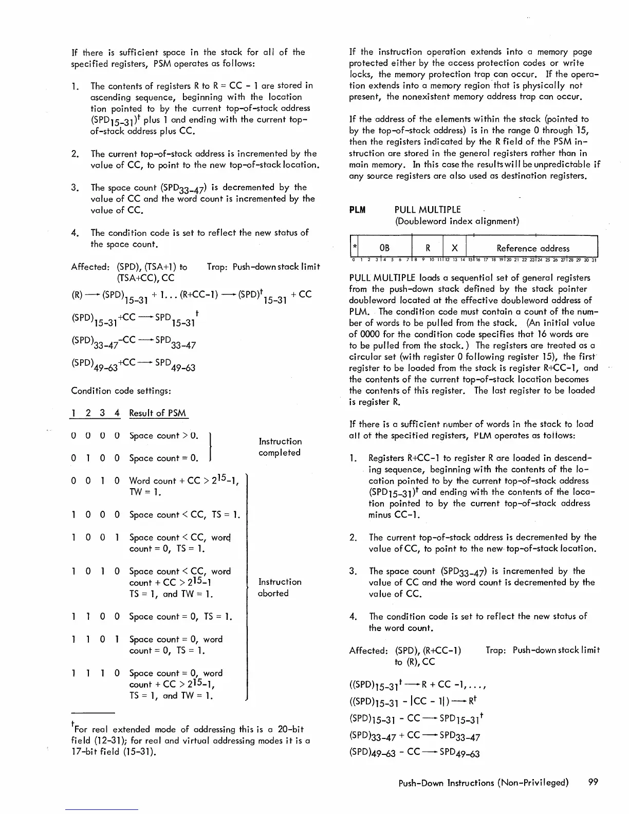
PLM
PULL
MULTIPLE
(Doubleword
index
alignment)
PULL
MULTIPLE
loads a sequential
set
of
general
registers
from the push-down
stack
defined by the
stack
pointer
doubleword
located
at
the
effective
doubleword address
of
PLM.
The
condition
code
must
contain
a
count
of
the
num-
ber
of
words to be pulled from the
stack.
(An
initiaJ value
of
0000 for
the
condition code specifies
that
16
words
are
to be pulled from the
stack.)
The
registers are
treated
as a
circular
set
(with register 0 following register 15), the first
register to
be
loaded from the
stack
is register R+CC-1, and
the contents
of
the
current
top-of-stack
location
becomes
the
contents
of
this register.
The
last register to be loaded
is register
R.
If
there is a
sufficient
number
of
words in
the
stack
to load
all
of
the
specified
registers,
PLM
operates
as toiiows:
1. Registers
R+CC-1 to register R
are
loaded in
descend-
ing
sequence,
beginning with the contents
of
the
lo-
cation
pointed to by the
current
top-of-stack
address
(SPD15-31)t and ending with the contents
of
the
loca-
tion pointed to by the
current
top-of-stack
address
minus
CC-1.
2. The
current
top-of-stack
address is decremented by the
value
of
CC, to point to the
new"
top-of-stack
location.
3.
The
space
count
(SPD33-47)
is
incremented by the
value
of
CC and the word
count
is
decremented
by the
value
of
CC.
4.
The
condition
code is set to
reflect
the new status
of
the word
count.
Affected: (SPD), (R+CC-l)
to
(R),
CC
((SPDh5_31t-R
+CC
-1,
...
,
((SPD)15-31
-Icc
-
11)
-
Rt
(SPD)15-31 -
CC-
SPD
15-31
t
(SPD)33-47
+ CC - SPD33-47
(SPD)49-63
- CC - SPD49-63
Trap: Push-down
stack
limit
push-Down Instructions
(Non-Privileged)
99

 Loading...