January 2016
4-141
WorkCentre 4150/4250/4260WorkCentre WorkCentre 4150/4250/42604150/
REP 9.2, REP 9.3
Repairs and Adjustments
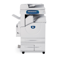
3. Remove the CRUM PWB, Figure 2.
Figure 2 PWB removal
Replacement
Replacement is the reverse of the removal procedure.
REP 9.3 Terminal Assembly
Parts List on PL 4.15
Removal
WARNING
Switch off the electricity to the machine. Disconnect the power cord from the customer
supply while performing tasks that do not need electricity. Electricity can cause death or
injury. Moving parts can cause injury.
WARNING
Take care during this procedure. Sharp edges may be present that can cause injury.
CAUTION
Before performing this procedure, refer to General Disassembly Precautions, GP 10.
1. Remove the exit tray assembly, PL 28.10 Item 1 or finisher (4265) REP 12.1.
2. Remove the paper exit cover, PL 28.10 Item 4.
3. Disconnect the following, according to machine model:
• (4150) CON1 on the HVPS
• (4250/4260) CON2 on the HVPS
• (4265) CN3, CN4 on the HVPS
4. Route the wire harness out the back of the machine.
5. Remove the main drive assembly, (4150) REP 4.1 or (4250/4260/4265) REP 4.3.
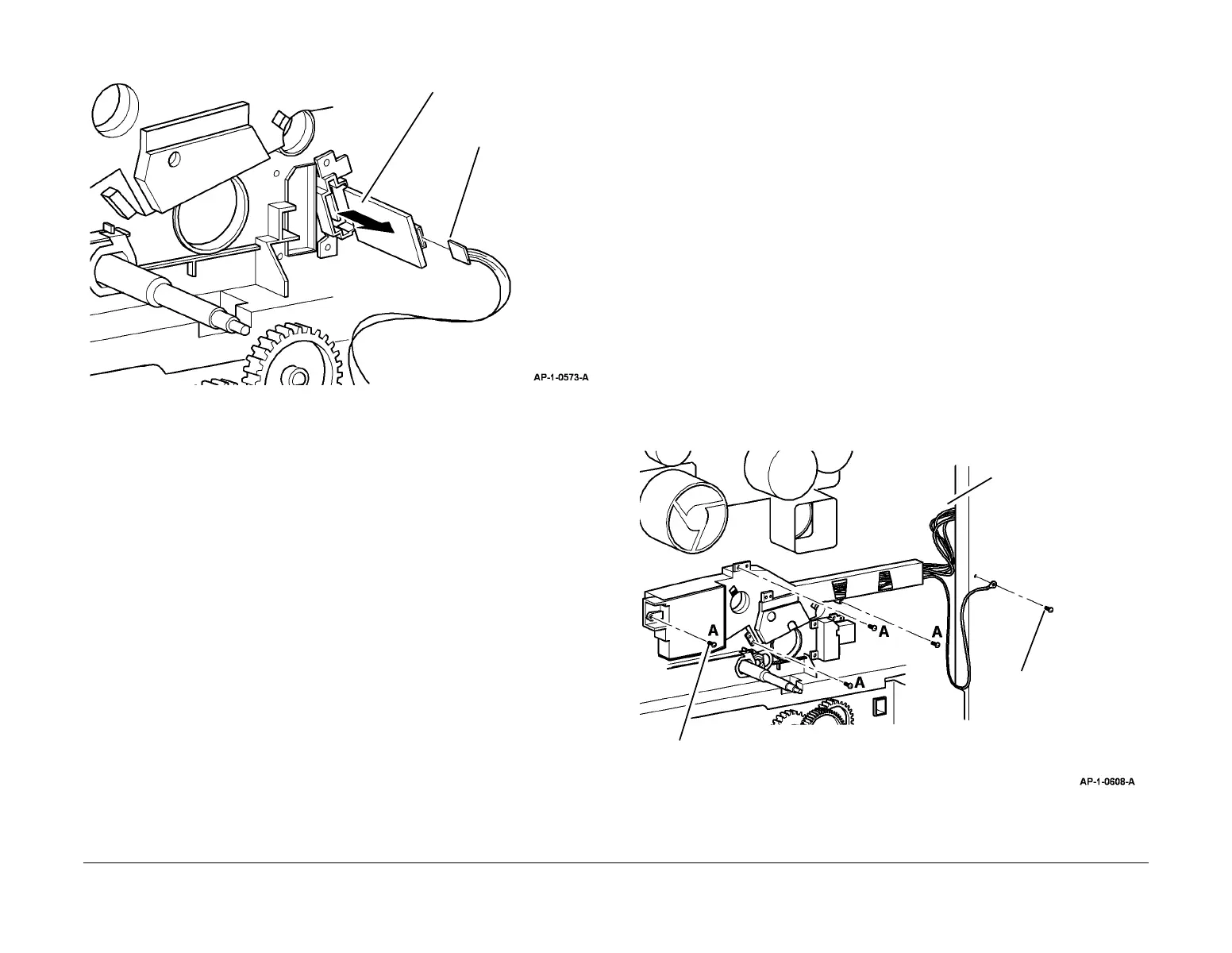
6. Remove the terminal assembly (Figure 1).
Figure 1 Terminal assembly removal
1
Remove the CRUM PWB.
2
Disconnect the
connector.
1
Remove 1 screw on
the ground strap.
2
Remove 4 mounting screws marked A.
3
Release the harness,
and remove the terminal
assembly.

 Loading...