Operation of the Transmitter Yamatake Corporation
5-48 ST3000 Smart Transmitter Series 900 Electronic Differential Pressure/Pressure Transmitter
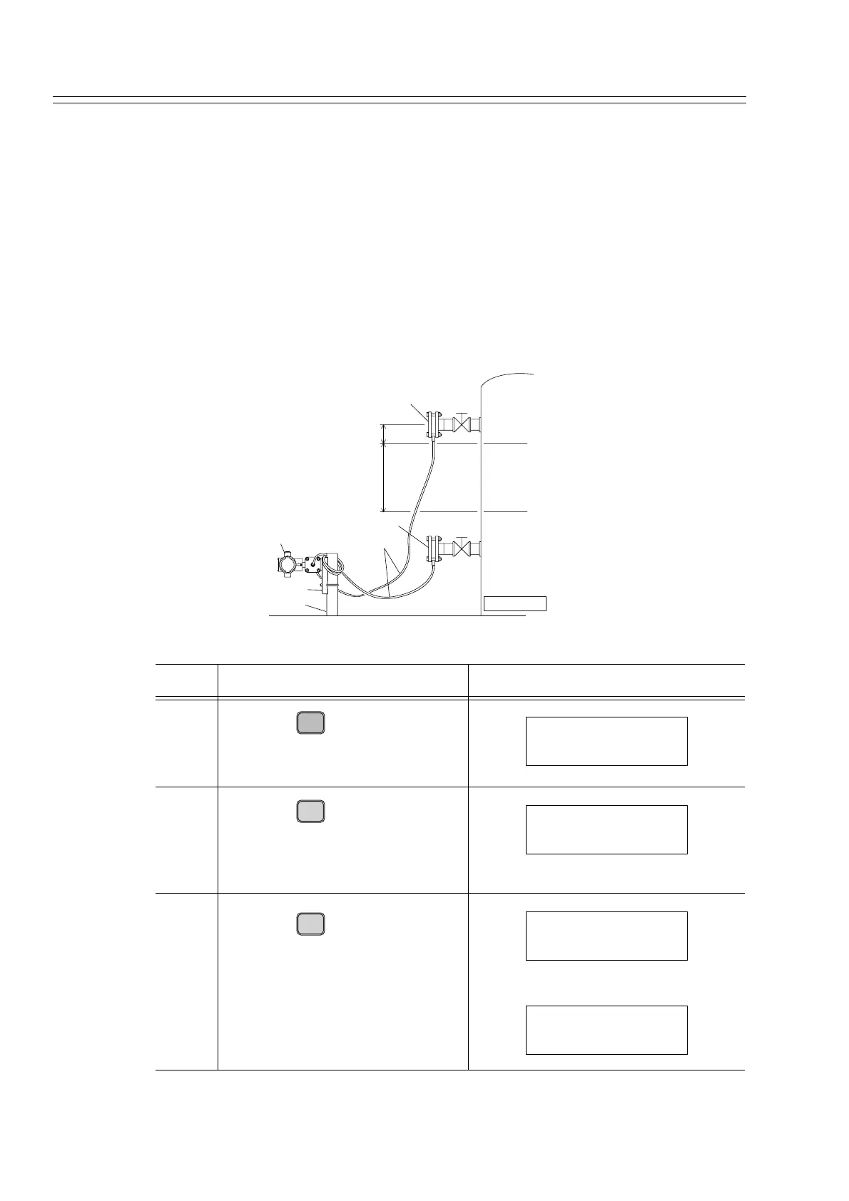
5-9 : Zero-span Adjustment with Input Pressure Equivalent to Range
The LRV (input pressure for 0% output) and the URV (input pressure for 100% out-
put) can be set based on the actual pressure by applying the pressure equivalent to the
desired range. The LRV and URV are set automatically based on the desired liquid
level or input pressure. Zero span adjustment is completed by this operation.
Procedure
Zero span adjustment procedure under the following conditions is explained below.
• Desired LRV value: 1050 mm (0%)
• Desired URV value: 50 mm (100%)
Procedure for setting LRV (input differential pressure at 0% output)
Step Description SFC screen
1
Press the key.
The current set value for LRV
will be displayed.
2
Press the key.
The SFC asks whether or not to
set the LRV based on the current
pressure.
3
Press the key.
The data will be loaded to the
memory of the transmitter and the
SFC and the new LRV value will
be displayed.
50mm
1000mm
100% liquid level
Tank
0% liquid level
High pressure side flange
Low pressure side flange
Capillary tube
Transmitter main unit
Mounting bracket
Pipe stanchion
Closed tank
LRV
E
0%
LRV FIT-1234
1050 mmH
2O
G
SET
LRV FIT-1234
SET LRV?
ENTER
( Yes )
NON-VOL
LRV FIT-1234
WORKING...
LRV FIT-1234
1050 mmH
2O