Operation of the Transmitter Yamatake Corporation
5-58 ST3000 Smart Transmitter Series 900 Electronic Differential Pressure/Pressure Transmitter
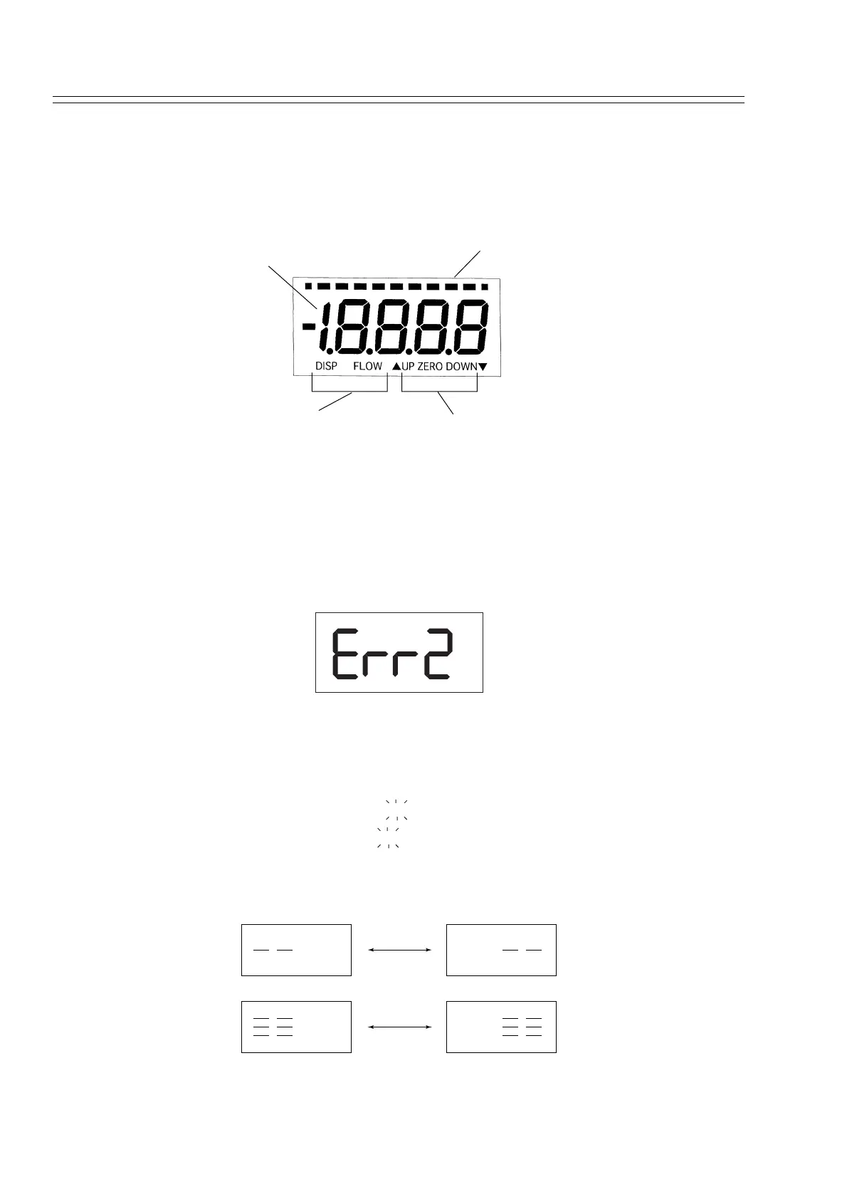
5-11 : Indicator (Option)
5-11-1 :Display Unit of Indicator
The display unit of an indicator consists of the following:
Figure 5-16 Display Unit of Indicator
5-11-2 :Digital Display
The indicator displays the output value of a transmitter in% or any engineering unit in
the digital mode. The display unit is a 4.5-digit 7-segment LCD. Indicates a value out-
side the display range by flashing as shown below.
• When the display value is within either of the following ranges, the limit
value flashes.
Range of display valueDisplay
Display value < -19999
Display value > 19999
• In some cases, a transmitter failure is indicated by the following display.
The response action is outlined in "7-6-4 : Self-Diagnostic by Indicator (option)".
Figure 5-17 Failure Display on Indicator
Bar graph display
Digital display
Linear / Square
root display
External zero point
adjustment display
-1999
1999